Installation, Operation and Technical Manual Rectifier Technologies
158-1872-01 6 19-Feb-14
to the monitoring and control module (MCSU-4) via an interface card (MUIB). This module
is in turn connected to the MCSU-4 magazine via a 34 way ribbon cable.
A 10-wire cable, which carries the digital communications signals that allow control and
monitoring of the rectifiers, connects the MCSU-4 to all the rectifiers in a parallel
arrangement so that all the rectifiers receive the same signal.
System status and operating parameters can be accessed from a PC connected to local
communication port on the front panel of the controller.
Remote monitoring of the system can be by means of voltage-free relay contacts.
Standard system uses 3 relays corresponding to SMR shutdown, System Alarm and High
Voltage Shut Down (HVSD).
Alternatively, a remote communication port can be used to display all the system and
rectifier information on a remote PC.
With this facility, it is possible to not only monitor but also control all the rectifier and
system parameters. In addition, the system has the capability to dial up to three telephone
numbers to connect to the remote PC in the event of a system fault having developed, and
will continue dialling until the fault is reported.
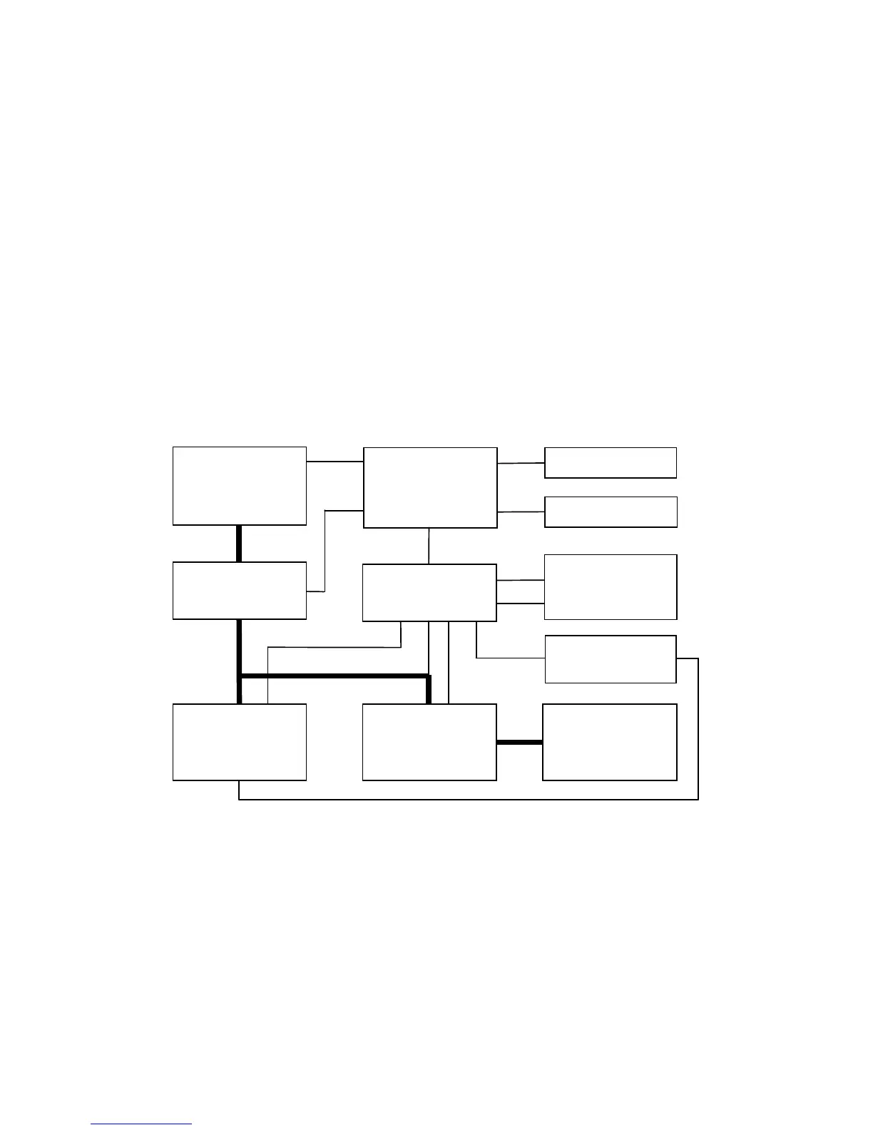
Figure 3.2 System with additional single phase AC Monitor
The second option shown in Figure 3.2 is the basic arrangement described above with the
addition of an auxiliary single phase AC monitoring module and Battery Cell Monitor. This
module, which is mounted in the AC distribution module, connects via a ribbon cable to the
MUIB and is used to monitor the AC voltage, current and frequency .
The third option shown in Figure 3.3 is the basic arrangement with the addition of an
auxiliary three phase AC monitoring module. The latter connects directly to the MCSU-4
via a ribbon cable and provides monitoring of the three AC voltages and currents as well
as the AC frequency. It has multiplexing circuits on board which effectively extends the
analogue monitoring ability of the MCSU-4.