Installation, Operation and Technical Manual Rectifier Technologies
158-1872-01 74 19-Feb-14
7. Commissioning
Commissioning primarily requires an understanding of the rectifier visual signals and
operator adjustable parameters on the system controller (MCSU-4). Before a system is
first energized, it is advisable to read this section thoroughly.
7.1 Indicators on the Rectifier Front Panel
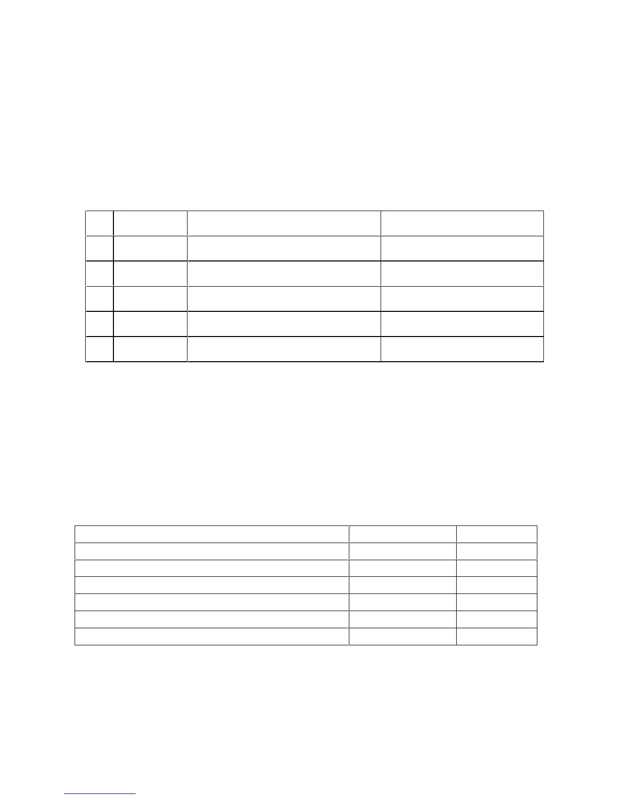
There are three LEDs on the front panel to indicate the operating status of the rectifier
modules. They are as follows:
Rectifier functioning normally
Input AC voltage out of range
Unit is in Equalisation mode
Red (with yellow LED flashing)
Unit is switched off or failed
If necessary, further information about the particular rectifier alarm condition, if one exists,
can be found by referring to the MCSU-4 or the PC connected to the MCSU-4 - see
detailed section on MCSU-4.
7.2 System Parameter Ranges
Range of adjustment and default settings of system parameters are contained in a table at
the beginning of this manual. Use last column to record parameters’ values set during
commissioning.
7.2.1 RT9 SMR Parameters
High Voltage alarm Threshold
Low Voltage alarm Threshold
HVSD Voltage alarm Threshold
7.3 System Commissioning
To commission a system, modification of system parameters on the MCSU-4 is required.
This can be done manually through the front panel of the MCSU-4 (see detailed section on
MCSU-4 operation), or by using a PC running WinCSU-2 that is connected to MCSU-4 via
the USB interface (see detailed section on WinCSU-2 operation). It is recommended for