Installation, Operation and Technical Manual Rectifier Technologies
158-1872-01 34 19-Feb-14
4.9.4 Installing the board
Generally, the BCM board is located close to the batteries so that it is not necessary to run
large number of wires for long distances. The 16 way ribbon cable connecting to the
MCSU-4 can be up to 10m long, but should be connected directly to the MCSU-4, instead
of connected at the end of another chain of peripherals. This helps reduce errors. This
connection can be achieved by using a ‘daisy chain’ ribbon where the one cable has
connectors placed part way along its length as well as the ends.
Mount the BCM using the standoffs supplied in an area protected from mechanical and
electrical hazards. If the rack does not provide any holes or studs for mounting the BCM,
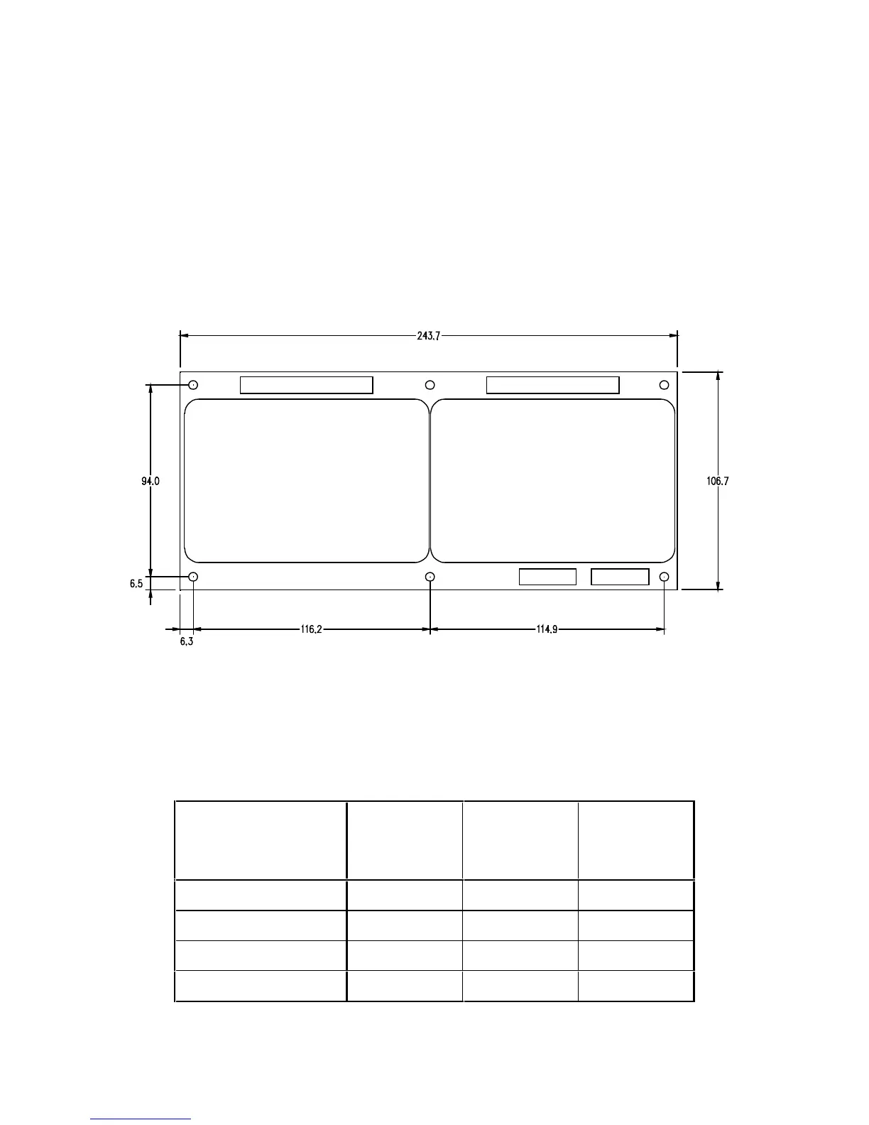
use Figure 4.10 as a template for drilling the mounting holes. Be sure to allow at least
25mm space around the board to allow for wiring to the board.
Figure 4.10 BCM mounting hole locations.
4.9.5 Dip-Switch Selection of Cell Voltages
Battery configuration is selected via the main menu of the MCSU-4, whereas the cell or
monoblock voltage must be selected via dip-switch S65 on the PCB. The following table
indicates the DIP-switch setting for different cell/monoblock voltages: