Installation, Operation and Technical Manual Rectifier Technologies
158-1872-01 5 19-Feb-14
3. Configuration
3.1 System Description
This Manual has been written with the objective of giving the reader a sufficient
understanding of the system and its constituent parts in order to be able to install,
commission and operate the system.
3.1.1 General Description
This modular system has been designed specifically to power 24V or 48V
telecommunications equipment requiring accurate temperature compensated Float and
Equalisation voltages, low output noise and EMI levels.
A typical system comprises a number of rectifiers, depending on the power requirement of
the system, and a monitoring and control subsystem comprising a monitoring and control
module (MCSU-4), a User Interface Board (MUIB) and optional modules for monitoring AC
power and battery cell voltages.
The system can be configured in a number of ways depending on the customer and
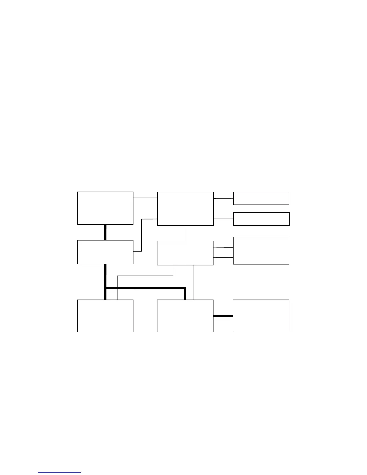
application requirements. The simplest option is shown in Figure 3.1.
Figure 3.1 System with basic monitoring and control
The AC Distribution may simply consist of circuit breakers, one for each magazine of
rectifiers in the system, or may also include an isolator, depending on customer
requirements.
The rectifiers housed in one or more magazines are paralleled and the DC output
connected to the load via the DC Distribution module and to the battery bank, which may
be a single battery or two (or more) batteries connected in parallel. A Low Voltage
Disconnect Switch (LVDS) may also be included in series with the batteries in order to
prevent over-discharging the battery bank in the event of an unusually long AC power
outage.
The monitoring and control signals, such as battery currents, temperature, battery switch
status, LVDS control and status, system voltage and ambient temperature are connected