Installation, Operation and Technical Manual Rectifier Technologies
158-1872-01 10 19-Feb-14
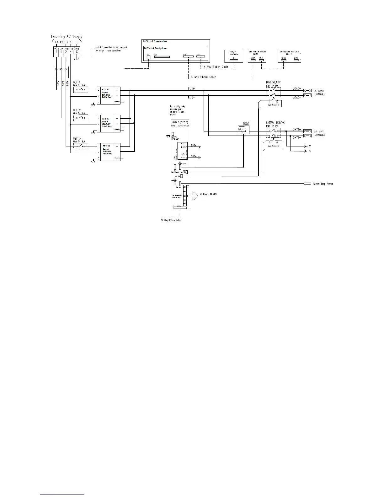
Figure 4.1 Typical System Wiring
Battery Current Transducers: A Hall effect current measuring unit that is installed over the
cable connecting the battery string to its circuit breaker. The signal lines are connected to
terminal on the MUIB.
Temperature Sensors: Modules typically assembled in a copper lug with a mounting hole
at one end and sensor cabling running from the other sealed end to terminals in the MUIB.
The sensors are normally placed in the battery compartment to measure battery
temperatures.
AC Monitoring Module: Optional modules are available in either single phase or three
phase models. The module connects in series with the incoming mains supply by having
the phase wires inserted through the current sensors on the module before having the
terminating at the active link. The phase-neutral (or phase-phase) voltages are separately
sensed by reference transformers. Inputs for voltage measurement are protected against
high voltage transients. The modules are connected to the MCSU-4 magazine via a 16-
way ribbon. If both types of modules are installed use the second 16-way connector on
single phase module for connection to the three phase module.
DC voltage regulation and power for the MCSU-4 is derived from the output DC bus via
the connections on the MUIB. The connection point is made where a constant voltage is
most useful. This is typically at the point where the cables run to the batteries. External
voltage sensing for voltage regulation at a load can also be done, but in most systems, the
system voltage is sensed on the internal output bus. For more information, see the
detailed section on the MUIB.