13
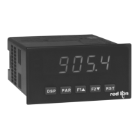
Resistance Signal
(3 wire requiring
excitation)
Terminal 3: Resistance
Terminal 5: Resistance
Terminal 6: Jumper to
terminal 3
Excitation Jumper:
1.75 mA REF.
3 4 5 6
10K MAX.
CURRENT
VOLT/OHM
+EXC
COMM
1.75 mA
REF.
Potentiometer Signal
(3 wire requiring excitation)
Terminal 3: Wiper
Terminal 5: Low end of pot.
Terminal 6: High end of pot.
Excitation Jumper: 2 V REF.
Input Range Jumper: 2 Volt
Module 1 Input Range: 2 Volt
Note: The Apply signal scaling style
should be used because the signal
will be in volts.
3 4 5 6
Rmin=1KΩ
CURRENT
VOLT/OHM
+EXC
COMM
2V REF.
2V
INPUT
Current Signal
(self powered)
Terminal 4: +ADC
Terminal 5: -ADC
Voltage Signal
(self powered)
Terminal 3: +VDC
Terminal 5: -VDC
Current Signal (2 wire
requiring excitation)
Terminal 4: -ADC
Terminal 6: +ADC
3 4 5
+
-
10 VDC MAX.
20 mA
PAXP INPUT SIGNAL WIRING
Current Signal (3 wire
requiring excitation)
Terminal 4: +ADC (signal)
Terminal 5: -ADC (common)
Terminal 6: +Volt supply
Voltage Signal (3 wire
requiring excitation)
Terminal 3: +VDC (signal)
Terminal 5: -VDC (common)
Terminal 6: +Volt supply
4 5
+
-
20 mA DC MAX.
20 mA
COMM
LOAD
3 4 5 6
20 mA
10 V
+24 EXC
COMM
+Vs
3 WIRE TRANSMITTER
COMM.IoutVout
4 5 6
20 mA
+24 EXC
COMM
2 WIRE
TRANSMITTER
-
+
+24V
CAUTION: Sensor input common is NOT isolated from user input common. In order to preserve the safety of the meter application, the sensor input
common must be suitably isolated from hazardous live earth referenced voltages; or input common must be at protective earth ground potential. If not,
hazardous live voltage may be present at the User Inputs and User Input Common terminals. Appropriate considerations must then be given to the
potential of the user input common with respect to earth common; and the common of the isolated option cards with respect to input common.
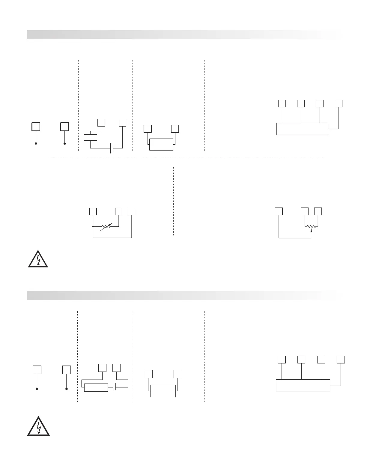
Current Signal
(self powered)
Terminal 4: +ADC
Terminal 5: -ADC
Voltage Signal
(self powered)
Terminal 3: +VDC
Terminal 5: -VDC
Current Signal (2 wire
requiring excitation)
Terminal 4: -ADC
Terminal 6: +ADC
Excitation Jumper: 24 V
3 5
+
-
VOLT/OHM
Before connecting signal wires, the Input Range Jumper and Excitation Jumper should be verified for proper position.
4.2 INPUT SIGNAL WIRING
Current Signal (3 wire
requiring excitation)
Terminal 4: +ADC (signal)
Terminal 5: -ADC (common)
Terminal 6: +Volt supply
Excitation Jumper: 24 V
Voltage Signal (3 wire
requiring excitation)
Terminal 3: +VDC (signal)
Terminal 5: -VDC (common)
Terminal 6: +Volt supply
Excitation Jumper: 24 V
4
5
COMM
Load
-
+
3 4 5 6
CURRENT
VOLT/OHM
+EXC
COMM
+Vs
3 WIRE TRANSMITTER
COMM.IoutVout
4 6
CURRENT
+EXC
2 WIRE
TRANSMITTER
-
+
+24V
PAXD INPUT SIGNAL WIRING
 Loading...


