15
Sourcing Logic
Terminals 9-11:
+ VDC through external switching device
Terminal 8:
-VDC through external switching device
In this logic, the user inputs of the meter are
internally pulled down with 22 K resistance.
The input is active when a voltage greater
than 3.6 VDC is applied.
USER 3
USER 2
USER 1
COMM
8 9 10 11
Sinking Logic
Terminals 9-11
Terminal 8
In this logic, the user inputs of the
meter are internally pulled up to +5 V
with 22 K resistance. The input is
active when it is pulled low (<0 .9 V).
Connect external
switching device between
appropriate User Input
terminal and User Comm.
+
(30V max.)
SUPPLY
V
USER 3
USER 2
USER 1
COMM
98
-
1110
}
PAXH ONLY
DSP
8.8.8.8.8
X
M
A
T
O
T
NMI
PAR
F1 F2
RST
A
1
S
P
S
P
S
2
3
PP4
S
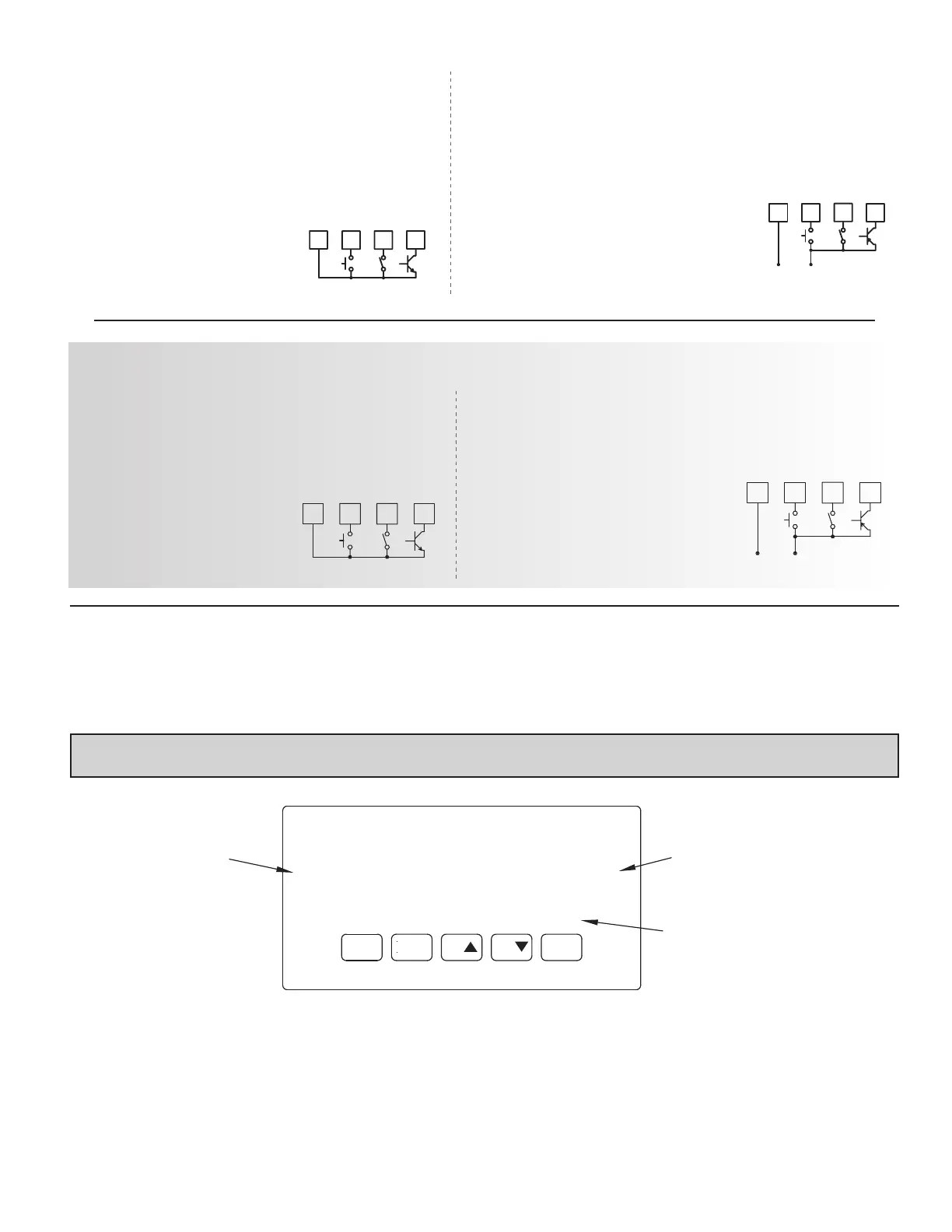
Display
Readout
Legends*
Optional Custom
Units Overlay
Setpoint Alarm
Annunciators
* Display Readout Legends may be locked out in Factory Settings.
** Factory setting for the F1, F2, and RST keys is NO mode.
RST
F2
F1
PAR
DSP
KEY
Hold with F1, F2
to scroll value by x1000 Reset (Function key)**
Decrement selected parameter valueFunction key 2; hold for 3 seconds for Second Function 2**
Increment selected parameter valueFunction key 1; hold for 3 seconds for Second Function 1**
Store selected parameter and index to next parameterAccess parameter list
Quit programming and return to display modeIndex display through max/min/total/input readouts
PROGRAMMING MODE OPERATIONDISPLAY MODE OPERATION
5.0 revieWing THe frOnT bUTTOns and display
4.4 SETPOINT (ALARMS) WIRING
4.5 SERIAL COMMUNICATION WIRING
4.6 ANALOG OUTPUT WIRING
See appropriate option card bulletin for details.
Sinking Logic
Terminal 8-10:
Terminal 7: }
In this logic, the user inputs of the
meter are internally pulled up to +5 V
with 22 K resistance. The input is active
when it is pulled low (<0 .9 V).
+
(30V max.)
SUPPLY
V
USER 3
USER 2
USER 1
COMM
87
-
109
4.3 USER INPUT WIRING
Before connecting the wires, the User Input Logic Jumper should be verified for proper position. If not using User
Inputs, then skip this section. Only the appropriate User Input terminal has to be wired.
Sourcing Logic
Terminal 8-10: + VDC thru external switching device
Terminal 7: -VDC thru external switching device
In this logic, the user inputs of the meter are
internally pulled down to 0 V with 22 K
resistance. The input is active when a voltage
greater than 3.6 VDC is applied.
USER 3
USER 2
USER 1
COMM
7 8 9 10
Connect external switching device between
appropriate User Input terminal and User Comm.
 Loading...


