27
Sending Commands and Data
When sending commands to the meter, a string containing at least one
command character must be constructed. A command string consists of a
command character, a value identifier, numerical data (if writing data to the
meter) followed by a the command terminator character * or $.
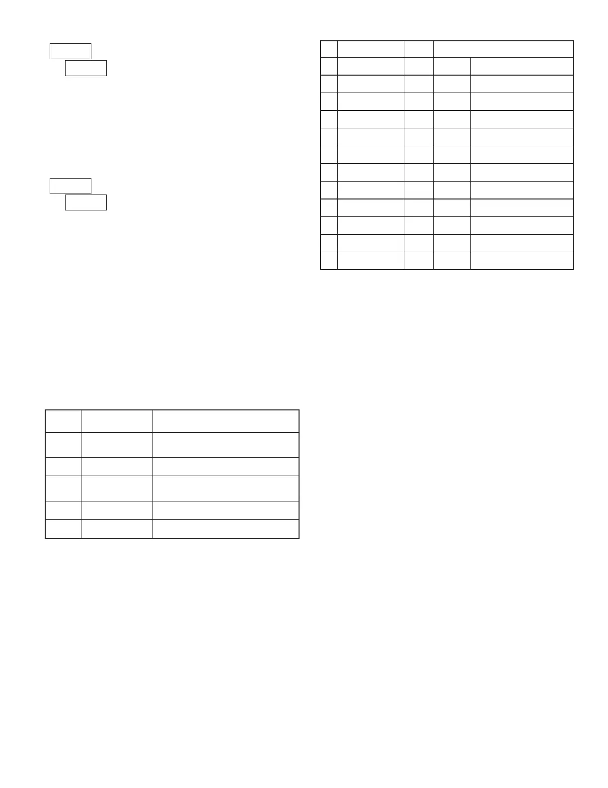
Command Chart
Command String Construction
The command string must be constructed in a specific sequence. The meter
does not respond with an error message to illegal commands. The following
procedure details construction of a command string:
1. The first 2 or 3 characters consist of the Node Address Specifier (N) followed
by a 1 or 2 character node address number. The node address number of the
meter is programmable. If the node address is 0, this command and the node
address itself may be omitted. This is the only command that may be used in
conjunction with other commands.
2. After the optional address specifier, the next character is the command character.
3. The next character is the register ID. This identifies the register that the
command affects. The P command does not require a register ID character. It
prints according to the selections made in print options.
4. If constructing a value change command (writing data), the numeric data is
sent next.
5. All command strings must be terminated with the string termination
characters * or $. The meter does not begin processing the command string
until this character is received. See timing diagram figure for differences of
* and $ terminating characters.
Command Description Notes
N
Node Address
Specifier
Address a specific meter. Must be followed by
one or two digit node address. Not required
when node address = 0.
T Transmit Value (read)
Read a register from the meter. Must be
followed by register ID character.
V Value change (write)
Write to register of the meter. Must be
followed by register ID character and numeric
data.
R Reset
Reset a register or output. Must be followed
by register ID character
P
Block Print Request
(read)
Initiates a block print output. Registers are
defined in programming.
Register Identification Chart
ID Value Description
Register
ID
Applicable Commands/Comments
A Input INP T, P, R
(Reset command [Ver2.5+]
zeros the input [“REL” or Tare])
B Total TOT T, P, R
(Reset command resets total to
zero)
C Max Input MAX T, P, R
(Reset command resets MAX
to current reading)
D Min Input MIN T, P, R
(Reset command resets MIN to
current reading)
E Setpoint 1 SP1 T, P, V, R
(Reset command resets the
setpoint output)
F Setpoint 2 SP2 T, P, V, R
(Reset command resets the
setpoint output)
G Setpoint 3 SP3 T, P, V, R
(Reset command resets the
setpoint output)
H Setpoint 4 SP4 T, P, V, R
(Reset command resets the
setpoint output)
I
Analog Output
Register
AOR T, V (Applies to manual mode)
J
Control Status
Register
CSR T, V
L
Absolute (gross)
input display value
ABS
GRS †
T, P
Q Offset/Tare (PAXS)
OFS
TAR †
T, P, V (Ver 2.5+)
Command String Examples:
1. Node address = 17, Write 350 to Setpoint 1, response delay of 2 msec min
String: N17VE350$
2. Node address = 5, Read Input value, response delay of 50 msec min
String: N5TA*
3. Node address = 0, Reset Setpoint 4 output, response delay of 50 msec min
String: RH*
Sending Numeric Data
Numeric data sent to the meter must be limited to 5 digits (-19,999 to 99,999).
If more than 5 digits are sent, the meter accepts the last 5. Leading zeros are
ignored. Negative numbers must have a minus sign. The meter ignores any
decimal point and conforms the number to the scaled resolution. (For example:
the meter’s scaled decimal point position = 0.0 and 25 is written to a register.
The value of the register is now 2.5 In this case, write a value = 25.0).
Note: Since the meter does not issue a reply to value change commands, follow
with a transmit value command for readback verification.
Receiving Data
Data is transmitted by the meter in response to either a transmit command (T),
a print block command (P) or User Function print request. The response from
the meter is either a full field transmission or an abbreviated transmission. In this
case, the response contains only the numeric field. The meter response mode is
established in programming.
Full Field Transmission
Byte Description
1, 2 2 byte Node Address field [00-99]
3 <SP> (Space)
4-6 3 byte Register Mnemonic field
7-18
12 byte data field; 10 bytes for number, one byte for sign, one byte
for decimal point (The T command may be a different byte length)
19 <CR> carriage return
20 <LF> line feed
21 <SP>* (Space)
22 <CR>* carriage return
23 <LF>* line feed
* These characters only appear in the last line of a block print.
The first two characters transmitted are the node address, unless the node address
assigned =0, in which case spaces are substituted. A space follows the node address
field. The next three characters are the register ID (Serial Mnemonic).
The numeric data is transmitted next. The numeric field is 12 characters long
(to accommodate the 10 digit totalizer), with the decimal point position floating
within the data field. Negative value have a leading minus sign. The data field
is right justified with leading spaces.
The end of the response string is terminated with a carriage return <CR> and
<LF>. When block print is finished, an extra <SP><CR> <LF> is used to
provide separation between the blocks.
PRINT OPTIONS
- Enters the sub-menu to select those meter parameters to appear in the
block print. For each parameter in the sub-menu select for the parameter to
appear with the block print, and to disable the parameter.
Gross Value (PAXS Only)
Tare Value (PAXS Only)
Input Value
Max and Min Values
Total Value
Setpoint values*
*Setpoints 1-4 are setpoint option card dependent.
ABBREVIATED PRINTING
Select abbreviated transmissions (numeric only) or full field transmission.
When the data from the meter is sent directly to a terminal for display, the extra
characters that are sent identify the nature of the meter parameter displayed. In
this case, select . When the data from the meter goes to a computer, it may be
desirable to suppress the node address and mnemonic when transmitting. In this
case, set this parameter to .
† -Register ID for the PAXS.
 Loading...


