26
Enter the probe burn-out action. In the event of a temperature probe failure,
the alarm output can be programmed to go on or off.
SETPOINT ANNUNCIATORS
PROBE BURN-OUT ACTION (PAXT ONLY)
Alternate Setpoints
An Alternate list of setpoint values can be stored and recalled as needed. The
Alternate list allows an additional set of setpoint values. (The setpoint numbers
nor rear terminal numbers will change in the Alternate list.) The Alternate list
can only be activated through a function key or user input programmed for
in Module 2. When the Alternate list is selected, the Main list is stored and
becomes inactive. When changing between Main and Alternate, the alarm state
of Auto Reset Action alarms will always follow their new value. Latched “on”
alarms will always stay latched during the transition and can only be reset with
a user input or function key. Only during the function key or user input
transition does the display indicate which list is being used.
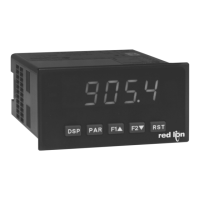
LARM
STATE
OFF
ON
Hys
SP
OFF
ON
OFF
OFF
ON
OFF
ON
OFF
OFF
ON
OFF
ON
OFF
MANUAL
RESET
SP - Hys
( Auto)
(LAtC1)
(LAtC2)
Setpoint Alarm Reset Actions
The mode disables display setpoint annunciators. The mode
displays the corresponding setpoint annunciators of “on” alarm outputs. The
mode displays the corresponding setpoint annunciators of “off” alarms
outputs. The mode flashes the corresponding setpoint annunciators of
“on” alarm outputs.
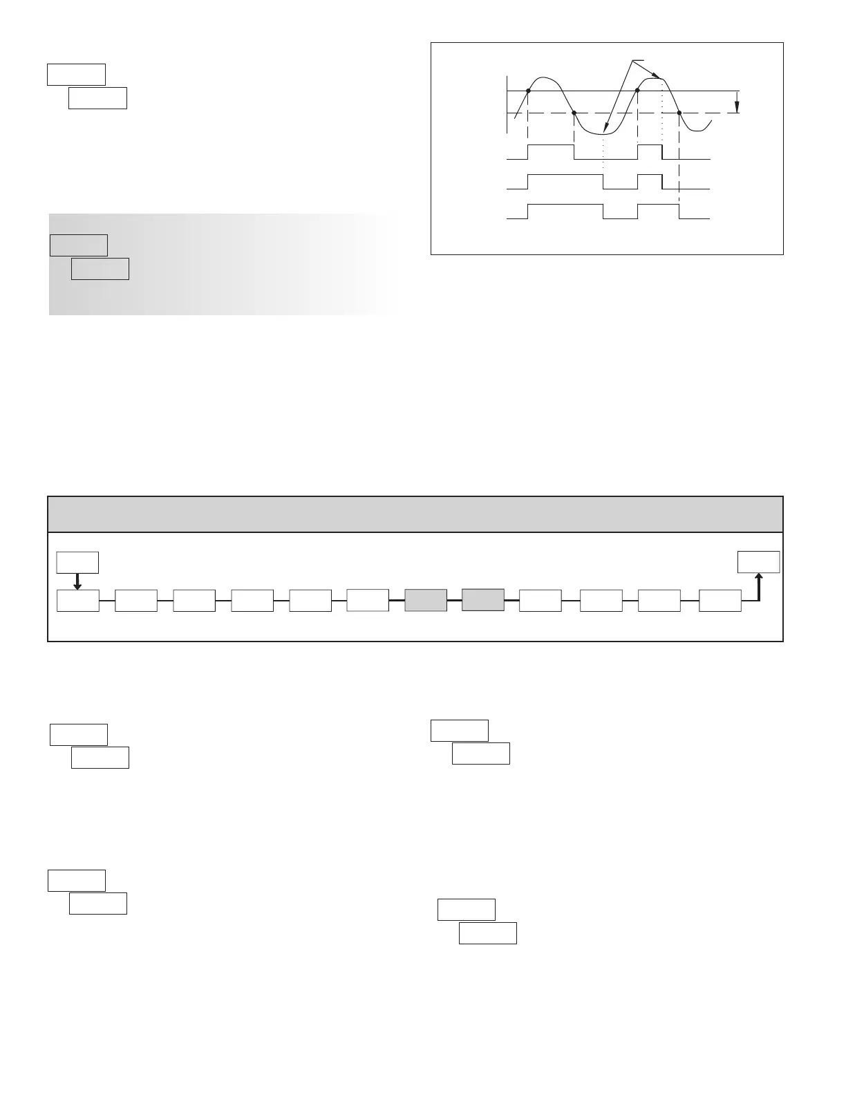
7-SrL
dAtA
Baud
Rate
bAUd
Parity
Bit
PAr
Print Total
Value
tot Addr
Meter
Address
Abrv
Abbreviated
Printing
Print Input
Value
INP SPNtHILO
PAR
Pro
Data
Bit
Print Max
& Min Values
Print Setpoint
Values
OPt
Print
Options
6roSS
Gross
tArE
Tare
PAXS
ONLY
PAXS
ONLY
6.7 mOdUle 7 - serial COmmUniCaTiOns parameTers () Ñ
PARAMETER MENU
DATA BIT
BAUD RATE
Set the baud rate to match that of other serial communications equipment.
Normally, the baud rate is set to the highest value that all of the serial
communications equipment is capable of transmitting.
Select either 7 or 8 bit data word lengths. Set the word length to match that
of other serial communication equipment. Since the meter receives and
transmits 7-bit ASCII encoded data, 7 bit word length is sufficient to request
and receive data from the meter.
Ñ - A communication card must be installed in order to access this module.
PARITY BIT
Set the parity bit to match that of the other serial communications equipment
used. The meter ignores the parity when receiving data, and sets the parity bit
for outgoing data. If no parity is selected with 7-bit word length the meter
transmits and receives data with 2 stop bits. (For example: 10 bit frame with
mark parity)
METER ADDRESS
to
Enter the serial node address. With a single unit on a bus, an address is not
needed and a value of zero can be used (RS232 applications). Otherwise, with
multiple bussed units, a unique address number must be assigned to each meter.
The node address applies specifically to RS485 applications.
 Loading...


