24
6-SPt
ACt-n
Setpoint
Select
SPSEL
Setpoint
Value
SP-n
Setpoint
Source
Src-n
Output
Logic
out-nHYS-n
Setpoint
Hysteresis
tON-n
On Time
Delay
Off Time
Delay
tOF-n
Standby
Operation
Stb-n
Reset
Action
rSt-n
PAR
Pro
Burn-out
Action
brn-n
Setpoint
Action
LIt-n
Setpoint
Annunciators
PAXT
ONLY
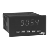
6.6 mOdUle 6 - seTpOinT (alarm) parameTers () Ñ
PARAMETER MENU
Enter the setpoint (alarm output) to be programmed. The in the following
parameters will reflect the chosen setpoint number. After the chosen setpoint is
completely programmed, the display will return to . Repeat step for
each setpoint to be programmed. The chosen at will return to .
The number of setpoints available is setpoint output card dependent.
SETPOINT SELECT
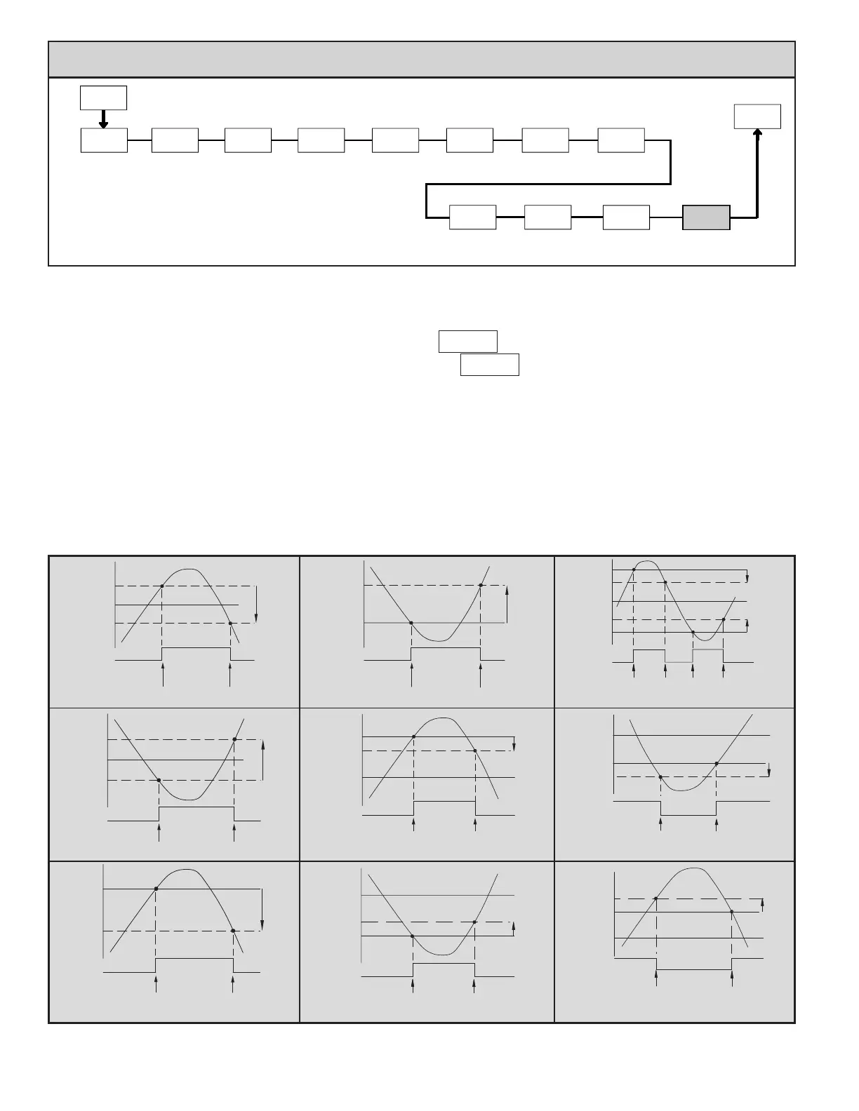
Setpoint Alarm Figures
With reverse output logic , the below alarm states are opposite.
ALARM
STATE
OFF
ON
Hys
SP + Hys
SP
OFF
TRIGGER POINTS
ALARM
STATE
ON
OFF
Hys
SP1 + (-SPn)
SP1
ON
TRIGGER POINTS
Absolute Low Acting (Unbalanced Hys) =
Deviation High Acting (SP
< 0) =
ALARM
STATE
OFF
ON
Hys
SP + ½Hys
SP
SP - ½Hys
OFF
TRIGGER POINTS
ALARM
STATE
OFF
ON
Hys
SP1 + SPn
SP1
OFF
TRIGGER POINTS
ALARM
STATE
ON
OFF
Hys
SP1 - (-SPn)
SP1
ON
TRIGGER POINTS
Absolute Low Acting (Balanced Hys) =
Deviation High Acting (SP
> 0) =
Deviation Low Acting (SP
< 0)=
ALARM
STATE
OFF
ON
Hys
SP
SP - Hys
OFF
TRIGGER POINTS
ALARM
STATE
OFF
ON
Hys
SP1 - SPn
SP1
OFF
TRIGGER POINTS
ALARM
STATE
OFF
ON
Hys
SP1 - SPn
SP1
OFF
SP1 + SPn
ON
OFF
Hys
TRIGGER POINTS
Absolute High Acting (Unbalanced Hys) =
This is also for Totalizer alarms: ,
Deviation Low Acting (SP > 0) =
Band Outside Acting =
ALARM
STATE
OFF
ON
Hys
SP + ½Hys
SP
SP - ½Hys
OFF
TRIGGER POINTS
Absolute High Acting (Balanced Hys) =
Depending on the card installed, there will be two or four setpoint outputs
available. For maximum input frequency, unused Setpoints should be configured
for action.
The setpoint assignment and the setpoint action determine certain setpoint
feature availability.
Ñ - A setpoint card must be installed in order to access this module.
 Loading...


