16
3. SYSTEM COMPONENTS
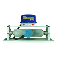
3.1. RML2000 Coriolis Mass Flowmeter
The Coriolis meter is mounted in a similar position to
a traditional volumetric meter at the rear of the truck.
The meter is connected in line via 2” 300 lb pressure
rated anges to the vapor release and differential
valve.
The meter is constructed from stainless steel and
consists of a double U-tube arrangement enclosed in
a rectangular case. The drive coil, used to vibrate the
tubes, and the sensor coils which measure the exing
of the tubes under ow conditions, are mounted inside
the box.
The instrument electronics are enclosed within the
small junction box at the top of the meter. Power and
communication connections to the register are made
here. The only means of communicating directly to the
Coriolis meter is to connect a computer to these same terminals. The computer is only required to “zero”
the meter as part of the calibration process, to be discussed later in this manual.
Once the junction box lid is closed, there are no operator controls on the meter; all functions are per-
formed at the E4000 register head.
3.2. E4000 Register Head
The E4000 electronic register is designed and eld proven to
withstand the harsh environment on tank trucks. The enclosure
is plastic with a NEMA 3 rating.
The E4000 can be mounted directly on the positive displace-
ment owmeter so that the mechanical drive of the meter rotates
an optical pulse encoder mounted in the register. Alternately,
the register can be mounted wherever required when receiving
a pulse output from a meter. Counting the pulses indicates the
amount of product measured by the owmeter during a delivery.
An optional temperature compensation kit can be added to the
base unit.
An operator communicates with the register via an LCD screen and a 4 button control panel. Internally
mounted relays operate electrical solenoid valves to control the ow of product. Delivery ticket information
is transmitted through the power/data cable from the rear of the register to a cab mounted junction box,
then to the ticket printer or hand-held computer.
Power and data connections are made to terminal strips inside the register and junction box. Congura-
tion parameters are programmed into the register manually by the buttons or from an external computer
using the E4000 conguration program.
An internal calibration switch is positioned inside the register to allow access to the Weights and Measures
conguration menu, and is mechanically sealed on the outside of the register.
Figure 3-1. RML2000 Tube Conguration
Figure 3-2. E4000 Register Head
 Loading...