Do you have a question about the Red Seal Measurement Neptune RML2000 and is the answer not in the manual?
| Brand | Red Seal Measurement |
|---|---|
| Model | Neptune RML2000 |
| Category | Measuring Instruments |
| Language | English |
Explains the purpose of warnings, cautions, and notes in the manual.
Outlines the terms of use, copyright, and liability for the manual's content.
Details essential precautions for safely handling electronic components sensitive to static discharge.
Information on the required Prolink 3 software for zeroing and configuration of RML Series meters.
Details power and data connections for the Modbus units.
Details power and pulse output wiring for the Pulse Output units.
Procedure for zeroing Modbus units using ProLink 3 software.
Procedure for zeroing Pulse Output units using the dedicated zero button.
Details using Prolink 3 for zeroing Pulse Output units.
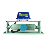
Describes the RML2000 Coriolis meter and E4000 electronic register system.
Details physical, flow, operating, and dimension specifications for the RML2000 meter.
Lists display, power, relay, valve, probe, and communication specs for the E4000 register.
Details custody transfer approvals and safety certifications (UL, CSA) for E4000 and RML2000.
Explains the construction and function of the RML2000 Coriolis meter.
Describes the E4000 register, its enclosure, mounting, and operator interface.
Details the E4000's display, keypad, and optional RTD temperature compensation.
Describes solenoid valves for flow control and the junction box's connectivity role.
Details printer and mobile computer connectivity for data management.
Outlines installation prerequisites, parts check, and truck preparation steps.
Covers mounting the RML2000 meter securely and correctly.
Details installing a retrofit RML2000 and positioning the E4000 register.
Explains how to install and wire the RTD temperature probe for compensation.
Guides on mounting and wiring the single stage LPG solenoid valve.
Details the installation and wiring for the dual stage LPG solenoid valve.
Continues the wiring instructions for the dual stage valve, including terminal connections.
Covers selecting a location and mounting the junction box and printer.
Details wiring connections for the E4000 register to valves and other components.
Explains how to connect power and data cables to the junction box terminal blocks.
Details connecting the RML2000 meter's power/encoder cable to the E4000 register.
Guides on installing the printer and connecting power to the junction box.
Details connecting the junction box to the truck's power sources and grounds.
Describes how to connect a mobile computer to the junction box for data access.
Introduces the main menus (Route, Supervisor, W&M) of the E4000.
Details operations in Route Mode and functions for supervisors.
Explains accessing and using the W&M mode for calibration.
Step-by-step guide to configure E4000 settings like serial numbers, units, and resolution.
Details settings for printer status check and RTD activation.
Steps to configure E4000 for RML meter, check voltage, and connect computer.
Detailed steps for connecting Prolink software to the meter and verifying settings.
Guides on checking and applying meter configuration settings in Prolink's Flow tab.
Details configuration parameters for Density and Frequency tabs in Prolink.
Covers enabling transmitter options and the procedure for warming up the meter.
Step-by-step guide to perform a mass flow zero calibration using Prolink.
Instructions before calibration, including printing shift reports and selecting Route mode.
Steps to navigate the E4000 to the volume calibration menu.
Guides on selecting product, class, and entering K-Factor manually.
Steps for performing an automatic calibration using a volumetric prover.
Details entering prover volume and calculating the new K-Factor.
Steps to verify K-Factor accuracy and temperature compensated volume.
Steps to print a calibration report from the E4000 unit.
Comprehensive checklists for junction box, register, and printer installation.
Final checks for LPG solenoid valves and system operation after installation.
Steps to reset the E4000 to factory defaults, including RTD recalibration.
Guides on re-entering calibration, product, and system data after initialization.
Information on managing and recycling end-of-life E4000 materials.
Lists specific materials requiring proper disposal or recommended for recycling.
Chart to convert wire colors between E4000 end, Belden, Carol, and junction box end.