31
4.16 Installing the Printer
The Epson TM-U295 printer is available with the E4000.
Find a suitable location in the cab for the printer. End
user requirements may vary but a commercially available
stand is recommended to secure the printer. Bolt the
printer stand to a sturdy section of the cab oor and
attach the printer with Velcro strips (gure 4-21). Remove
the printer’s rubber feet to get maximum holding force
from the Velcro.
Data and power cables are supplied with the printer kit
and junction box. The printer power cable is prewired to
the printer power terminal of the junction box as shown
in gure 18. Plug the power connector into the round
DC24V port as marked on the rear of the printer. The
9-pin connector on the printer data cable plugs into the
printer data socket provided on the junction box. Attach the
25-pin end of the data cable to the RS-232 socket
on the rear of the printer. (Note: To ensure proper
operation, use only the cable supplied with the printer.)
In the E4000 software under Supervisor>Com
Ports>Printer>Handshaking, set Handshaking to
“Hardware”. All of the DIP switches on the bottom of the
printer should be off (gure 4-22). (This is for software
EA.01.05.E and later versions.)
4.17 Connecting Power to the Junction Box
The junction box for the E4000 Electronic Register includes a voltage regulator to ensure that the unit
receives clean power within the appropriate voltage range. The box comes prewired for printer power and
truck power connections, and has an in-line 5A fuse on the power input (gure 4-24).The E4000 junction
box includes three wires for connecting to truck power (gure 4-25).
Figure 4-21. Printer Installation
Figure 4-22. Printer DIP Switches
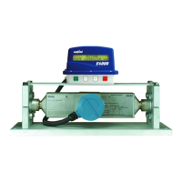
Figure 4-23. Junction Box (Voltage Regulator on
Right)
Figure 4-24. In-line 5A Fuse Holder
 Loading...