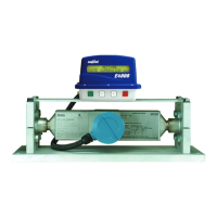
26
4.13 Installing the Junction Box and
Printer
Select a suitable location in the cab to
position the junction box so that the two
RS-232 ports are easily accessible and
the junction box cover can be removed for
service (gure 4-13). Route the 40 ft. power/
data cable from the E4000 register head
at the rear of the truck before permanently
xing the junction box. Route the cable away
from sharp edges, drive train components,
hot exhaust components, or other sources
of potential damage. It is recommended that
the cable be run through liquid-tight conduit
for protection.
The junction box dimensions are 10.5” x 7”.
Select a suitable location, orient the box, and
mark and drill the bolt holes in the mounting
surface. The mounting holes are accessible
from inside the box. Route the power and data cables to the junction box. Secure excess cable to prevent
damage.
4.14 Wiring the E4000 Register Head
The supplied 40 ft. power/data cable connects the E4000 and the cab mounted junction box.
Run the power/data cable the length of the truck from the owmeter to the cab and into the area selected
for the junction box. Automotive conduit is recommended to protect the cable from the environment.
Secure the cable to the truck frame or existing truck wiring using cable ties. Route to avoid moving body
parts, (drive shaft, etc) and sources of high temparature.
Some drilling may be required to pass through plating at the back of the truck and through bulkheads into
the cab. Placing grommets or watertight ttings on any holes to prevent cable damage is required.
The power/data cable should pass through the right side port of the E4000 register as viewed from the
rear (gure 4-17).
Make the connections as shown in the wiring diagrams for the E4000 register (gure 4-14, single-stage
valve or gure 4-15, dual-stage valve). The colors of the wires are shown in the diagram for identication
purposes. The numbers correspond to the E4000 terminal strip position to which the wire is connected.
See gure 4-16 for an example of proper wire routing and connection.
Caution: The drain (shield) wire should be cut off on the register end to prevent interference with power or
data lines. The drain wire is connected at the junction box end only.
Caution: Factory supplied plastic cable glands and metal liquid tight connectors prevent moisture
from entering the E4000 Register. Rubber gaskets should be installed over the threads of the
conduit hubs so that they are on the outside of the register base. Teon tape should be used
to seal the plastic cable gland and metal conduit nipple where they are inserted into the conduit
Figure 4-13. Junction Box Installation
 Loading...