20
4. INSTALLATION
4.1. Introduction
Before attempting to install an RML2000/E4000 system, read this manual! To simplify installation and
reduce the time required, follow the directions provided in this document. Each installation will vary
depending on the layout and overall condition of the truck, the uid being measured, and the installer’s
experience with electronic registers and owmeters.
WARNING: LPG systems should be installed in accordance with national standards ref: NFPA
58. Power, input and output (I/O) wiring must be in accordance with Class I, Division 2 wiring
methods Article 501-4(b) of the National Electrical Code, NFPA 70 for installations in the U.S., or as
specied in Section 18-1J2 of the Canadian Electrical Code for installations within Canada and in
accordance with the authority having jurisdiction.
4.2. Check Parts
Before commencing installation, unpack the entire contents of the E4000 packaging. Lay out the parts as
they would be installed on the truck. This will highlight any missing or incorrectly ordered/supplied parts.
Verifying that all the necessary parts are available in advance will reduce the truck downtime and avoid
any wasted truck preparation work.
4.3. Truck Preparation
Before commencing the installation:
Check that the condition of the truck battery is within the E4000 specications.
Disconnect the battery.
Close the manual supply valves and bleed down the meter.
Disconnect the pressure line from the top of the differential valve.
Warning: Pressure must be completely relieved before proceeding.
4.4. Installing the RML2000 Mass Flowmeter
The unit must be mounted using the approved bracket available from Red Seal (or a similarly fabricated
bracket that will hold the unit securely, place no stress on the meter, and transmit minimal vibration). The
four bolts securing the clamps which hold the meter should be torqued to 55-65 ft-lbs. The bolts attaching
the top plate (for mounting the register) should be torqued to 15-17 ft-lbs.
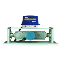
The unit should be mounted horizontally so that the electronics module faces outward (gure 4-1).
Figure 4-1. RML2000 in Bracket
 Loading...