21
The meter may be mounted for either left or right handed ow; however, the ow of liquid through the
meter must always be in the direction indicated by the arrow on the meter housing. (Left to right ow when
the unit is viewed with the nameplate on the right.)
Isolate the meter with valves upstream, downstream, and in the vapor return line, as close to the meter as
practicable. The valves are required to ensure the meter remains lled with propane during the “zeroing”
procedure. (see section 5).
Use exible hose (min. length 8”) for connections to both the inlet and outlet of the meter to eliminate
stress on the meter due to misalignment of piping. (See Figure 4-2, tank to meter inlet, and Figure 4-3,
differential valve to hose reel.).
Figure 4-2. Flexible Hose at Inlet Figure 4-3. Flexible Hose at Outlet
4.5. Installing a Retrot RML2000 Mass Flowmeter
The installation procedure for a retrot RML2000 is essentially the same as for a new installation. The
vapor release and differential valve from a previous Neptune 2” 4D-MT meter can be reused. If the prior
installation used mechanical temperature compensation, the installer will be required to replace the strain-
er cover with one that accommodates the E4000 thermowell. (See section 4.7, Installing the RTD). The 80
mesh strainer can be replaced with 16 mesh. (80 mesh is acceptable but will result in reduced ow and
more frequent cleaning,)
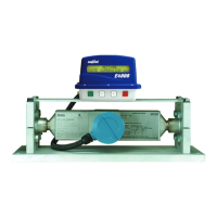
4.6. Positioning the E4000 Register Head
The RML2000 bracket supplied by Red Seal
provides a mounting plate with pre-drilled holes
for the E4000 (gure 4-4). If this bracket is not
used, the installer will be required to manu-
facture a custom xture to secure the register.
When considering a position for the bracket,
ensure that the register controls will be easily
and safely accessible by a driver. Also, the RTD
probe cable must reach to the vapor release
strainer cover as discussed in Section 4.8, Wir-
ing the RTD.
Figure 4-4. E4000 Mounted on Bracket
 Loading...