Page 14 of 28
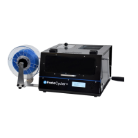
Figure 9: Light Guide V1.0 (left). Light Guide V1.1 (right).
3.6.1 What you need to check Light Guide Alignment:
• You’ll need two sizes of dowels. Drill bit shafts are an excellent option (use the smooth shank, not the
cutting flutes side). It’s very important that the dowels are a consistent, known size - DO NOT use extruded
filament!
• ReDeTec uses a 1.83mm and a 2.56mm dowel to align the light guides, but you can use anything close within
+/- 0.1mm. The larger dowel size is used for the sensor closest to the nozzle, and the smaller dowel size is
used for the sensor closest to the puller wheel. For reference we will call these the Puller Sensor and the
Nozzle Sensor.
• You will also need to be connected to a computer, to use ProtoCycler Command Center (“PCC”).
3.6.2 Light Guide Alignment Overview:
With ProtoCycler connected to PCC, start manual mode extrusion via the ProtoCycler U.I. (For guidance, refer to the
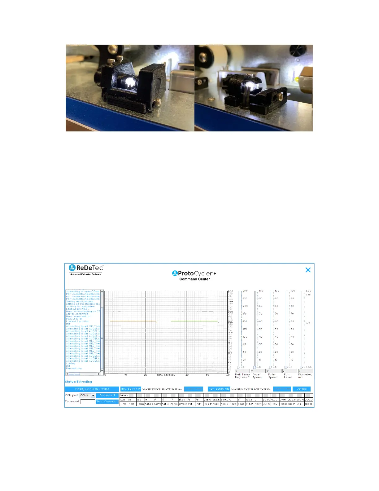
ProtoCycler Command Center Overview). You will see a screen that looks like this upon manual mode startup:
Figure 10a: Startup screen of manual extrusion with all readings toggled off (by clicking the “Labels” button above
the “Time” readout).
The two flat lines seen in Fig 10a above represent the raw data read by the light sensor photoresistor array for the
diameter of filament at the nozzle (left - brown line) and the final diameter of the filament at the puller wheel (right