Page 15 of 28
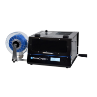
- dark green line). These lines being flat at a value of 255 (with a small amount of “drop-off” on the right) is a good
sign that your light guides are well aligned. If the light guides are lower than 255 or have severe angle to them, such
as Fig 10b below, alignment is required.
Note that “Alignment” refers to two separate tasks. The first is to ensure the light is evenly lighting the sensor. The
second is to ensure that the readings are accurate.
Figure 10b: Two examples of incorrectly aligned light guides – the nozzle is very bad, but the puller still has far too
much drop off on the right side to work.
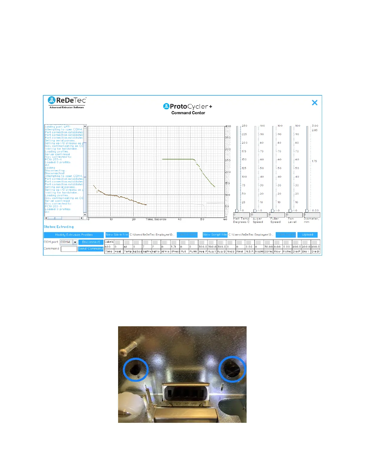
3.6.3 Step 1 - Adjusting the sensor height
1. The first step is to ensure the sensors themselves are aligned. Each sensor has a thumbscrew that, if
loosened, permits the sensor to move up and down, as shown below in Fig 11. The sensors are adjusted
from the factory and neither sensor should be adjusted unless the filament is seen to be frequently
“falling off the edge” of the sensor, as shown in Fig 19 (see “Extrusion - Automatic Mode”)