Page 17 of 28
3.6.5 Step 3 - Calibrating the readings
1. Finally, we need to ensure the light guide readings are accurate. This is where we’ll use the dowels. The
procedure is the same for both the puller and nozzle sensor, with minor differences that will be noted as
required.
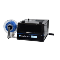
2. Place the ~1.83mm “dowel” in between the puller wheels as shown in Figure 13. Similarly, check the nozzle
sensor using your ~2.56mm dowel of choice. Do your best to align the dowel with the nozzle output as seen
in Figure 13. Make sure the puller idler wheel’s spring is attached! This will effectively position the dowel
at the right height as it squishes the puller wheel into position.
Figure 13 shows the light guide alignment dowel positioned in between the puller wheels on the left, and
aligned with the nozzle on the right, in preparation for light guide alignment.
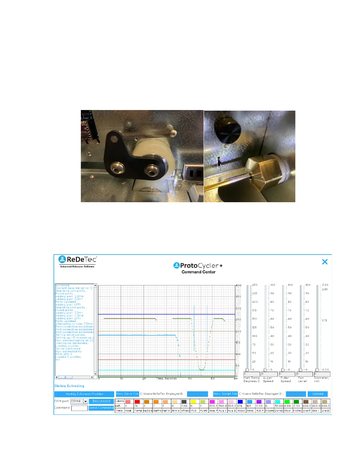
3. Looking at the GUI (graphical user interface) of your PCC, you should notice that the flat raw data line
(representing light being read by the photoresistor) is now a “U-shaped” trough. This is representative of
the shadow cast by the LED shining on the dowel, and is shown below in Figure 14.
Figure 14: Puller sensor raw data reading with 1.83mm dowel.