Page 16 of 28
Figure 11: UI Thumbscrews for adjusting the height position of the photoresistors.
2. Typically the puller sensor’s photoresistor will be positioned all the way at the bottom range of its
movement for best results. It has been adjusted this way from the factory, and should not need
adjustment!
3. The nozzle sensor is a little more tricky depending on what material is being extruded and at what diameter;
both of which will affect how the filament passes the first diameter sensor at the nozzle. Typically, the
nozzle diameter sensor’s photoresistor will be positioned ~1mm (~0.04”) above the midpoint of its range
of motion. The nozzle sensor’s photoresistor height can also be fine tuned during operation; this will be
addressed in the extrusion instructions of this manual.
4. If adjustment is required, loosen the thumbscrew holding that sensor, and move the sensor up and down.
Take extreme care to ensure the sensor remains correctly oriented in its slot - it cannot be angled or
offset sideways, or it will be impossible to align the LED lights.
3.6.4 Step 2 - Evenly lighting the sensor
1. If the sensor is not evenly lit (Fig 10b), the LED needs to be re-aimed to ensure that the response curve
shown in Fig 10a is obtained. The process is the same for both the Nozzle and Puller sensors.
2. Both light guide versions 1.0 and 1.1 allow the LED to be angled up or down, to ensure the light guide is
evenly lit. Their operation differs however - see step 3 for version 1.0 and step 4 for version 1.1
3. Version 1.0 has two screws facing “up”, which push on opposite sides of a lever to angle the LED shaft. To
aim the LED up, first loosen the front screw (farther from the user), then tighten the back screw (closer to
the user). To aim the LED down, first loosen the rear screw, then tighten the front screw. Adjust the LED
incrementally, monitoring the response pattern shown on the screen until it is an even response as shown
in Fig 10a. Finally, ensure both screws are snugged down to prevent further movement. Always loosen one
screw before tightening the other. Also, be sure to not overtighten the screws - they should just be snug.
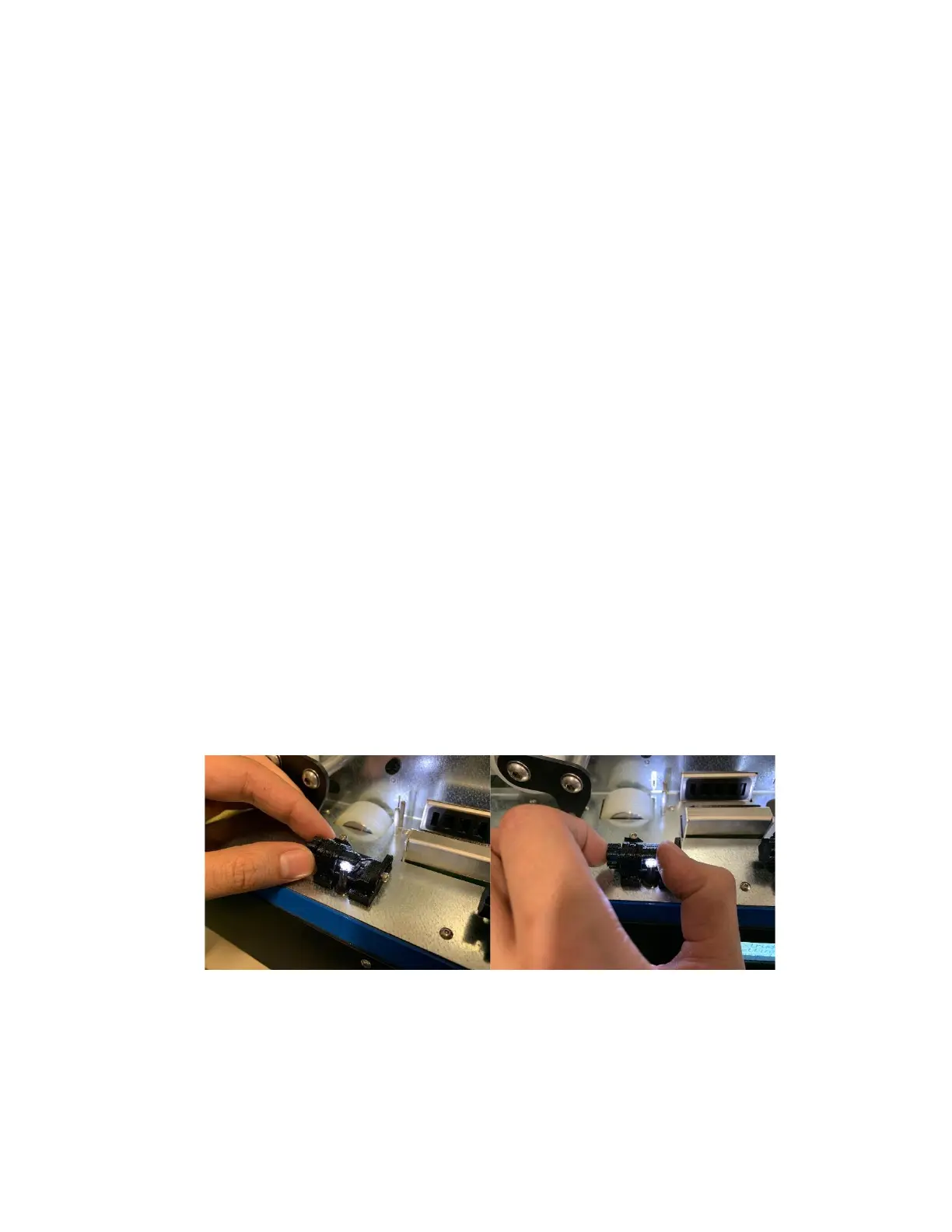
4. Version 1.1 has only one screw facing “up”, that clamps the LED shaft in position. To adjust the LED, first
loosen the screw. Then use the shaft knob on the left side of the light guide to adjust the angle of the LED.
You may want to support the other end of the shaft with your thumb for more control - see Fig 12 below
for reference. When the desired response pattern as shown in Fig 10a is obtained, simply re-tighten the
screw.
Figure 12: How to grip the light guide shaft to adjust LED angle.