EOS2 SAFETY LIGHT CURTAIN
OPERATION AND TECHNICAL DATA
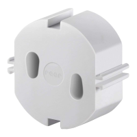
Light signals
The leds on the Emitter and Receiver light up according to system operating conditions.
Refer to the tables below to identify the various indications (ref.
Figure 23).
EMITTER RECEIVER
2
1
Figure 23 - Light signals
Emitter light signals
THREE-COLOUR LED
MEANING
(Red/Green/Orange)
System power-on. Initial TEST. RED
FAIL condition (Table 18)
2
RED BLINKING
TEST condition ORANGE
Normal operating condition
3
GREEN
Table 13 – TX light signals
Receiver light signals
LED
MEANING
TWO-COLOUR (Red/Green) (2) YELLOW (1)
System power-on. Initial TEST. RED ON
BREAK condition (A) RED OFF
GUARD condition (C) GREEN OFF
FAIL condition (Table 18) OFF
RED BLINKING
3
Table 14 – RX light signals EOS2 / EOS2 Slave
LED
MEANING
TWO-COLOUR (Red/Green) (2) YELLOW (1)
System power-on. Initial TEST RED ON
BREAK condition (A) RED OFF
CLEAR condition (B) OFF ON
GUARD condition (C) GREEN OFF
FAIL condition (Table 18) OFF
RED BLINKING
3
Table 15 – RX light signals EOS2 (With integrated control functions)
English
2
The type of fault is identified by the number of flashes (see Troubleshooting chapter)
3
Double blinking (at power-on) of the GREEN led indicates that high range has been selected.
22 8540738 • 2nd December 2009 • Rev.2