Equipment Operation
6-5
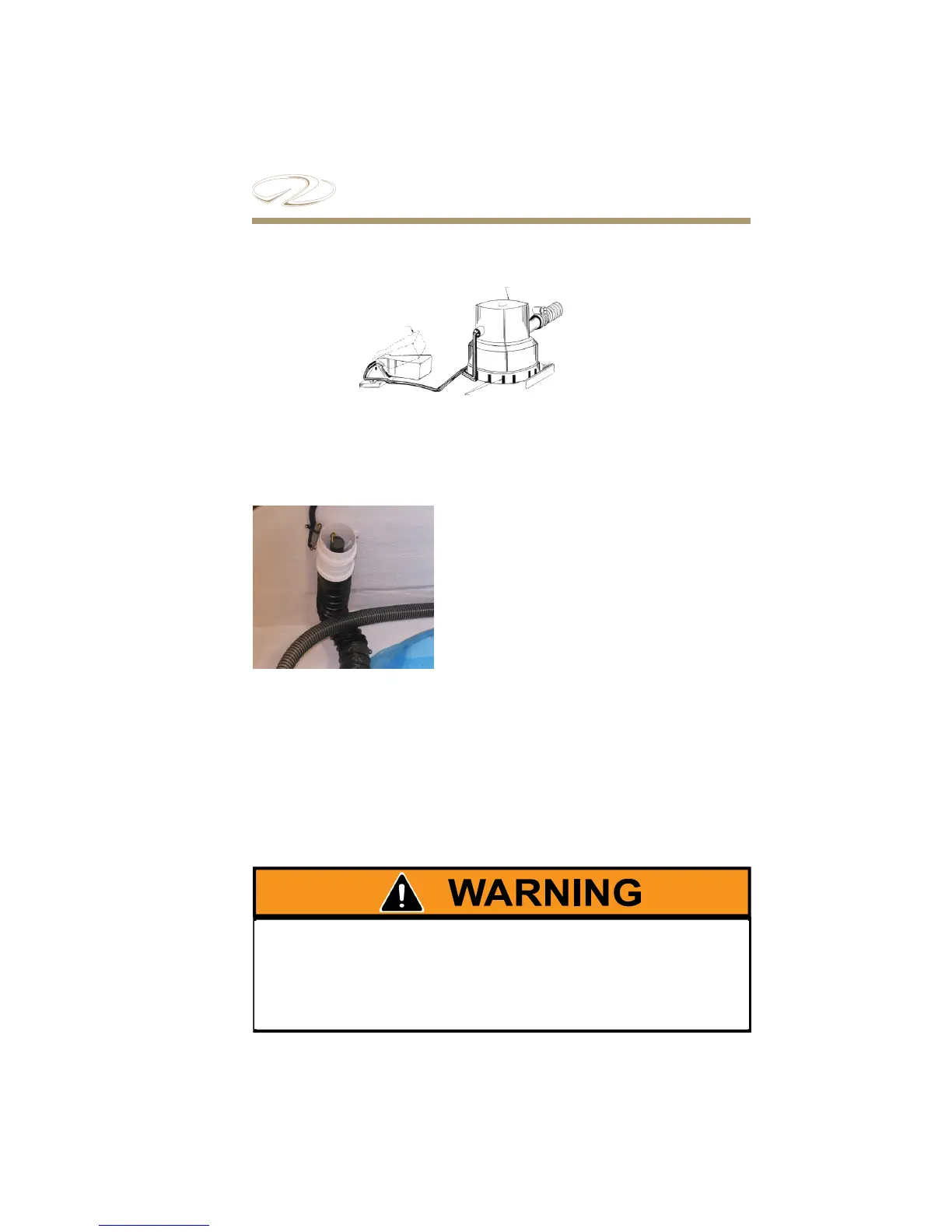
Typical Bilge Pump And Automatic Switch Diagram
BLOWER
On stern drive models a switch at the
helm controls the bilge blower. e
blower must be activated and run at least
4 minutes prior to starting the engine.
e fan cycle removes air from the
engine compartment. It is connected to
the ventilation hoses reaching the lower
1/3 of your bilge. e blower must be
operated below cruising speeds.
For safety requirements on blower use, refer to the safety on
board chapter. For switch control location, refer to the engine and
controls chapter. Refer to the systems chapter for electrical system
explanations. Refer to the vessel operation chapter for pre-departure
use. Refer to the technical chapter for sump schematics.
GASOLINE VAPORS CAN EXPLODE. BEFORE STARTING THE ENGINE,
OPERATE BLOWER FOR 4 MINUTES. VISUALLY CHECK AND SNIFF
THE ENGINE COMPARTMENT FOR GASOLINE LEAKS OR VAPORS.
ALWAYS RUN BLOWER BELOW CRUISING SPEEDS.
Typical Blower