TESTING CONCEPTS AND RECOMMENDED TEST SEQUENCE
18
VoIP Wiring and Using the TALAN VoIP Adapter
Traditional Telecom Cables
Typical analog and digital phone systems use a “reversed” modular 8-
conductor cable (where Pin 1 on one end of the cable corresponds to Pin
8 on the other end of the cable, Pin 2 to Pin 7, and so on). Flat modular
cords are most often in this reversed format. This reversed wiring can be
seen in the image at the right (note the reversed colored conductors on
each connector).
The TALAN can be used “in-line” with a phone system using the TALAN’s two modular jacks
which are identified as LINE and PHONE. The modular jacks on the TALAN are wired straight
through to allow for most common telephone systems without the use of a special crossover or
special test adapter cable. Pin 1 on the LINE jack corresponds to Pin 1 on the PHONE jack and so
on.
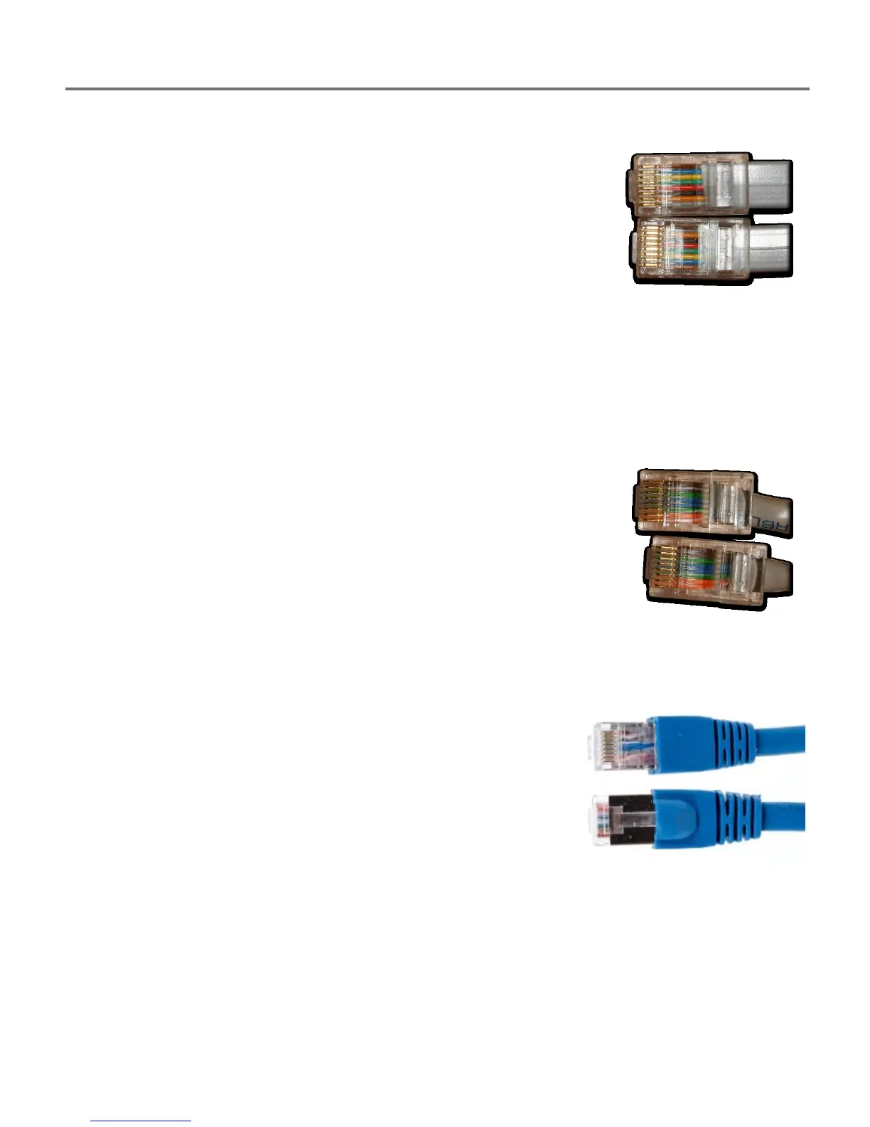
Cat5 Cables
Unlike the reversed modular flat cables found in most voice systems, Cat5
twisted pair cables, which are used in VoIP phone systems and some
digital phone systems, are wired in a “straight though” manner (Pin 1 to
Pin 1, Pin 2 to Pin 2, etc.). Typically, VoIP systems use Pins 1, 2, 3 and 6 of
an eight wire twisted pair cable. This straight through wiring is shown in
the image to the right (note the colored conductors are in the same order
in both connectors).
Cat6 Shielded Cables
CAT6 cables are based on the CAT5 design, however, CAT6
cables utilize shielding and potentially a drain wire and/or braid
to help reduce interference between conductors and also help
reduce interference between the CAT6 cable and other cables.
However, this additional shielding could be used as a carrier for
electronic information. For example: placing one lead of a
microphone on the shield and placing the other lead of the
microphone to one of the 8 CAT6 conductors.
TALAN 3.0 provides methods to test MOD8 conductors against
shields in CAT6 shielded cables.
 Loading...