7
13912-101 Rev. B
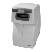
Parts Identification
1. Canthus Alignment Marks (right and left side):
Alignment mark that indicates the vertical position of
the center of the patient’s eye.
2. Operator Display:
Operator Display that displays measurement data.
3. Control Buttons:
Buttons used to select the Icons displayed on the Op-
erator Display.
4. Printer Door:
Door (push to open) to access travel lock and printer
paper.
5. Top Cover:
Outside top cover that provides access to the optical
head assembly.
6. Forehead Rest :
Alignmentmechanismthatmovesright/leftforcorrect
patient positioning.
7. Nosepiece Objective:
Airtube where “air puff” is emitted.
8. RS-232C Port:
Communication port that transfers printer data.
9. Main Power Connector & Fuse Holder:
Connection point for input power and the fuses.
Press the top tab and bottom tab together on the fuse
panel to remove the fuse holder and fuses.
10. ON/OFF Switch:
Switch that controls input power to the unit.
“O” indicates OFF, and “—” indicates ON.
11. Printer Paper Advance Button:
Button for advancing the printer paper and setting the
printeroff-line/on-line.
12. Travel Lock:
Locking mechanism that secures the internal parts of
the unit during shipment.
13. Printer:
Thermal printer supplied with the unit.
9
10
11
12
13
Figure 6, Parts Identification
Instrument Setup (Continued)
1
2
3
4
5
6
7
8

 Loading...