8
Location of Control System Sensors
Inlet Air Temperature Sensor (NS 120)
Control and anti–freeze sensors must always be situated
behind the heater, respectively cooler – to measure the sup-
ply air temperature. ey must not be situated in the room.
VO antifreeze protection sensor (NS 130R)
e return water temperature sensor must be situated in
the return water line from the water heater so that it will be
sufficiently bathed in water. e heating water circuit must
ensure all the required functions for the water heater control
and safety when the unit is shut down (filling the system
with antifreeze mixture) as specified in the air-handling
device project documentation. A capillary tube can be used
as additional antifreeze protection. If it is not installed on the
air-handling unit by the manufacturer, the capillary tube must
be run (meandering way) through the entire cross-section of
the water heater’s rear side.
Outdoor air temperature sensor (NS120)
Ideally, it should be situated in the outside environment – only
then are the control system’s functions ensured even in the
STOP mode or immediately aer unit start-up (e.g. moderate
pre-heating of the exchanger based on the actual outside
temperature, etc.).
If the sensor is situated in the fresh air inlet duct inside the
building, the measured temperature is only correct when the
fans are switched on (air flows) and the starting conditions
are negatively affected – which can endanger the air-handling
device’s safety and even result in the water heat exchanger
breaking down.
Outdoor Temperature Sensor
– installed outside (NS110A)
e sensor (as with any thermometer) must be installed
so that objective outdoor temperature measurement will
be achieved. It must be protected against negative effects
like sunshine, rainfall, frost deposits, e.g. situating it under a
building’s roof, using outdoor VZT roofs, situating it in the inlet
louvers, inlet ducts or separate covering roof.
Room Temperature Sensors
Optionally, a room (NS100), duct (NS120) or HMI-SG control-
ler integrated sensor can be used by the designer.
Commissioning
EO Pre-Heating Control Temperature Sensor (NS 120)
To ensure correct control, the sensor must be situated behind
the electric pre–heater (EO) – before other temperature
adjusting components.
Flue Gas Temperature Sensor
e Pt 100 sensor is used to measure the flue gas tempera-
ture. e sensor must be situated in a representative place
within the flue gas installation.
Inlet Air Humidity Sensor
is is a duct sensor which must always be situated in an inlet
branch aer the air-handling unit. e selected position must
be representative enough for the measured value. It must not
be situated in the room.
Room Humidity Sensor
Optionally, a room or duct sensor can be used by the designer.
n e room sensor must be situated in the room in a "rep-
resentative" place so that it will not be influenced by local
effects (windows, doors, etc.)
n e duct sensor must be situated in the outlet duct from
the room – the advantage here is that the mean humidity of
the room outlet air is measured.
TH 167 Gas Heating Safety ermostat
e sensor must be situated before the gas heater section
behind the fan section. e thermostat must be situated so
that it will start the fans to protect the air-handling compo-
nents situated in front of the gas heater chamber if back air
flow occurs.
Air Quality Sensor – CO
2
(VOC, CO)
e air quality sensors are placed in the outlet air duct or in
the "representative" spots, thus ensuring objective air quality
value measuring.
Connection of the fan frequency inverters,
heat exchanger to the Modbus bus
Safety Conditions
n Properly carried out transport, storage, installation, com-
missioning and careful handling is the main condition for
correct and trouble-free operation.
n Protection, switching, wire routing and grounding must
fully comply with the local regulations applicable for wiring.
n e 230/400 V AC power wiring must be strictly separated
from the signal wiring (e.g. 24 V AC SELV)!
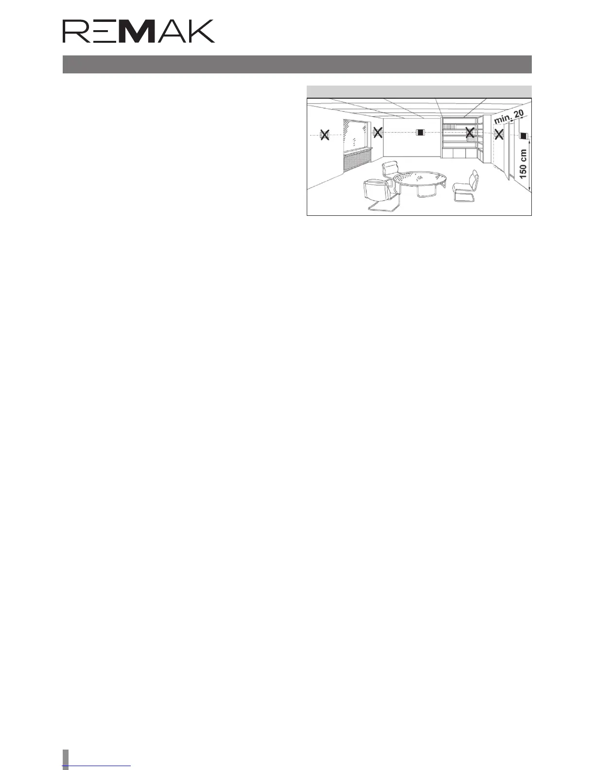
Figure 9 – Room sensor installation
• e room sensor or HMI-SG controller with integrated room
sensor must be situated in a spot "representing" the room tem-
perature, and they must not be affected by local effects (heaters,
windows, vertical temperature distribution in the room, etc.)
• e duct sensor must be situated in the room outlet duct
– the advantage in this is that the average temperature of the
air flowing from the room is measured without being affected
by local effects (and it is hidden).
Heat Exchanger's Antifreeze Protection Sensor
(NS 130R)
e sensor must be situated in the outlet air duct behind the
heat exchanger.