111
Control units VCS
Unit Activation
Unit Activation
Check the correct interconnection of the control unit and air-
handling unit. Check the motors (frequency inverters) - power
part, controls, dampers, filter pressure sensors, motors, sen-
sors… - in accordance with the air-handling unit.
Check the locations of the sensors, check the mechanical parts
(dampers, motors) for free rotation and sticking.
Fan pressure and differential pressure sensing hoses must
be situated so that they will sense static pressure (the end of
the hose must not be oriented against the air flow. It must
be oriented perpendicularly or in the direction of the air flow).
Depending on the operating mode, a large quantity of con-
densate can be created inside the unit. Before starting the
unit, it is advisable to check the condensate drainage circuit,
especially the correct height of the siphons (according to the
fan pressure), correct interconnection of the siphons – indi-
vidual siphons must not be hermetically connected, filling
of siphons with water and free passage through the piping.
Differential Pressure Sensor Setting Inspection
On the filters: Set the value of the final pressure loss in ac-
cordance with the rating plate data.
On the heat exchanger: e values are also indicated on the
rating plate. ey are derived from the operating pressure loss
of the heat exchanger.
If the results of the inspection are OK, connect the distribution
board to the power supply but still maintain the STOP mode.
Enter the "Inputs" item in the service menu of the controller
and check the state and functionality of the digital inputs (by
short circuiting the cable ends or disconnecting the cable).
Stay in the "Inputs" item in the service menu of the control-
ler and using the documentation check that the displayed
values for the sensors correspond to reality (compare with a
calibrated thermometer). If in doubt about the correct sensor,
disconnect the sensor and check the displayed value.
Check the position of the dampers (inlet and outlet dampers
closed, short-circuit damper open), failure-free operating state.
If the system indicates a failure, trace the failure, check the
component indicating the failure and remove the failure.
If no failures are indicated, test/simulate possible failures. At-
tention! Some failures can only be recalled when the device is
running, e.g. air flow failure. Reset the failures.
Go to the service menu of the controller and test in sequence
individual elements of the unit (dampers, heat exchanger,
heater, heat pump, circulation pumps and fans). Switch to
manual mode and test functionality (positions of damper,
opening of valves, direction of turning of fans). Once the testing
is finished, return all items to the AUTO mode.
Note: is way of testing ensures switching off in case of a
failure. When testing by direct switching of the outputs, no
protection is functional.
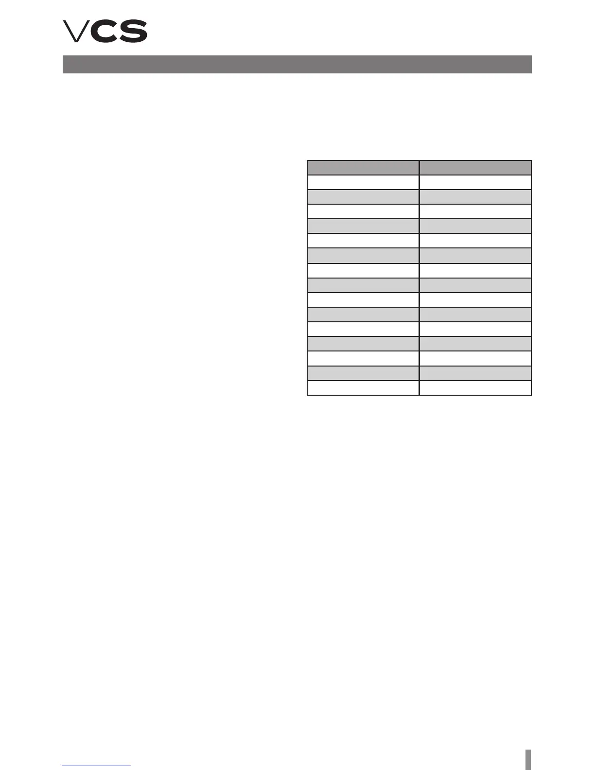
Impeller k-factor
RH 22 C 47
RH 25 C 60
RH 28 C 75
RH 31 C 95
RH 35 C 121
RH 40 C 154
RH 45 C 197
RH 50 C 262
RH 56 C 308
RH 63 C 381
RH 71 C 490
RH 80 C 620
RH 90 C 789
RH 10 C 999
RH 11 C 1233
Unicon Air Flow Sensor Settings
Sensor operation (Mode) – set to 5.00
Adjust measuring range in Pa (in accordance with max. pres-
sure of the fan).
Set the k-factor in accordance with the fan impeller type,
see Table.