16
Control and Protection Functions
Fan Speed Control
e VCS control unit enables either soware or manual air
output control, i.e. the speed of the following fans:
n Single-speed fans (ON/OFF control)
n Two-speed fans (two-stage control)
n Single-speed fans’ backup (ON/OFF control)
n Five-stage TRN voltage controllers
n Fan frequency inverters using the Modbus bus – five-stage
control
A standard control can be completed with a 3rd auxiliary fan
which is controlled from the outlet or inlet fan depending on
the control unit configuration.
Two-Speed Fans
e two-speed fans are always started using the first stage
at the air-handling unit start-up. e transition time from the
first to second stage can be adjusted. e transition time can
also be adjusted for the reverse transition from the second
to the first stage.
TRN Voltage Controllers
e control unit enables the voltage controllers to be con-
nected and controlled in five output stages. Depending on the
request, inlet and outlet control can be common or independ-
ent. e required output stage is always set in common. If
the fans are controlled independently, it is possible to set the
outlet controller correction against the inlet controller (see
the Data Point Settings – TRN Correction). However, the
control unit must be specially manufactured for this function
(depending on the customer request). Either the same cor-
rection can be set for all the speed stages or for each speed
stage independently. For the correction settings, refer to the
chapter Optional Function and Mode Settings.
Frequency Inverters
For five-stage control devices, the request for the inlet and
outlet fan speed is set in common. However, for frequency
inverters, the request for the inlet and outlet fan output
(0-100%) can be set separately for each stage (1 to 5) (see
the Data Point Settings – Fans).
Single-Speed Fan Backups (ON/OFF Control)
e backup motor is started if the main motor fails. e
backup is used either for the inlet or outlet fan, respectively
for both. e motors are equipped with thermal protection
(thermo-contact) and current protection. If the backup mo-
tor has been started, it is not possible to restart the main
motor without resetting the failure. e main and backup
motor current protection has a delay pre-set. Switching from
the main to backup motor is immediate without delay if the
main motor fails.
Backup fan control via Modbus communication bus
Using the Modbus communication bus, the five-stage fan
control enables a backup fan or a pair of backup fans to start
up if the main fan fails. If the backup fan or pair of backup fans
fails, the air-handling unit will be shut down. Information about
air-flow failures and motor overheating is sent via the Modbus
communication bus and signalled accordingly.
e fan speed control parameters are available through the
HMI controller in the List of Data Points in the section Settings
– Fans (inlet fan backup, outlet fan backup, TRN correction).
Constant Air Flow/Pressure Control
When designing constant flow, pressure, overpressure and
underpressure control, it is advisable to consider the overall
design of the air-handling unit, respectively application of the
mixing damper, and how the control behaviour can affect the
measured pressure value.
Constant Air Flow Control
Fan speed is controlled depending on the desired air flow rate
(m
3
/h). e air flow rate (air pressure in the diffuser recalcu-
lated to the air flow rate using the "k-factor") is measured by a
sensor; the control system evaluates this value and compares
it with the required value. e resulting fan speed is controlled
so that the required air flow rate will be reached at the point
of measurement (fan diffuser).
It is necessary to set the following pressure sensor pa-
rameters (see the Sensor Operating Manual):
n Mode (for CPG = Mode 5.00)
n Measuring range: As needed
e correct range can be determined
using a formula:
(where k = "k-factor", Vmax = designed air flow rate of the
device). e correct sensor range is then set according to the
calculated pmax value.
n K-factor of the respective fan
It is necessary to set the following parameters of the VCS
control Unit (see List of HMI Data Points):
n Air flow sensor measuring range – (maximum value from
the CPG air flow sensor in m
3
/h)
n is can be calculated using the formula or read from the
CPG sensor menu (see the Sensor Operating Manual).
n e maximum measured air flow rate can be calculated
according to the following formula:
V
max
= k × DP
max
Example: K-factor = 308, Maximum sensor range Pmax =
2000 Pa, Vmax = 13774 m
3
/h. is value is then entered
as the maximum range of the sensor in the VCS using HMI.
Note: In AC, the "Max. Air Flow Rate" is stated for the fan as-
semblies. Attention! is is not the maximum range of the air
flow sensor to be entered in the VCS control unit.
Dp
max
=
V
2
max
k
2
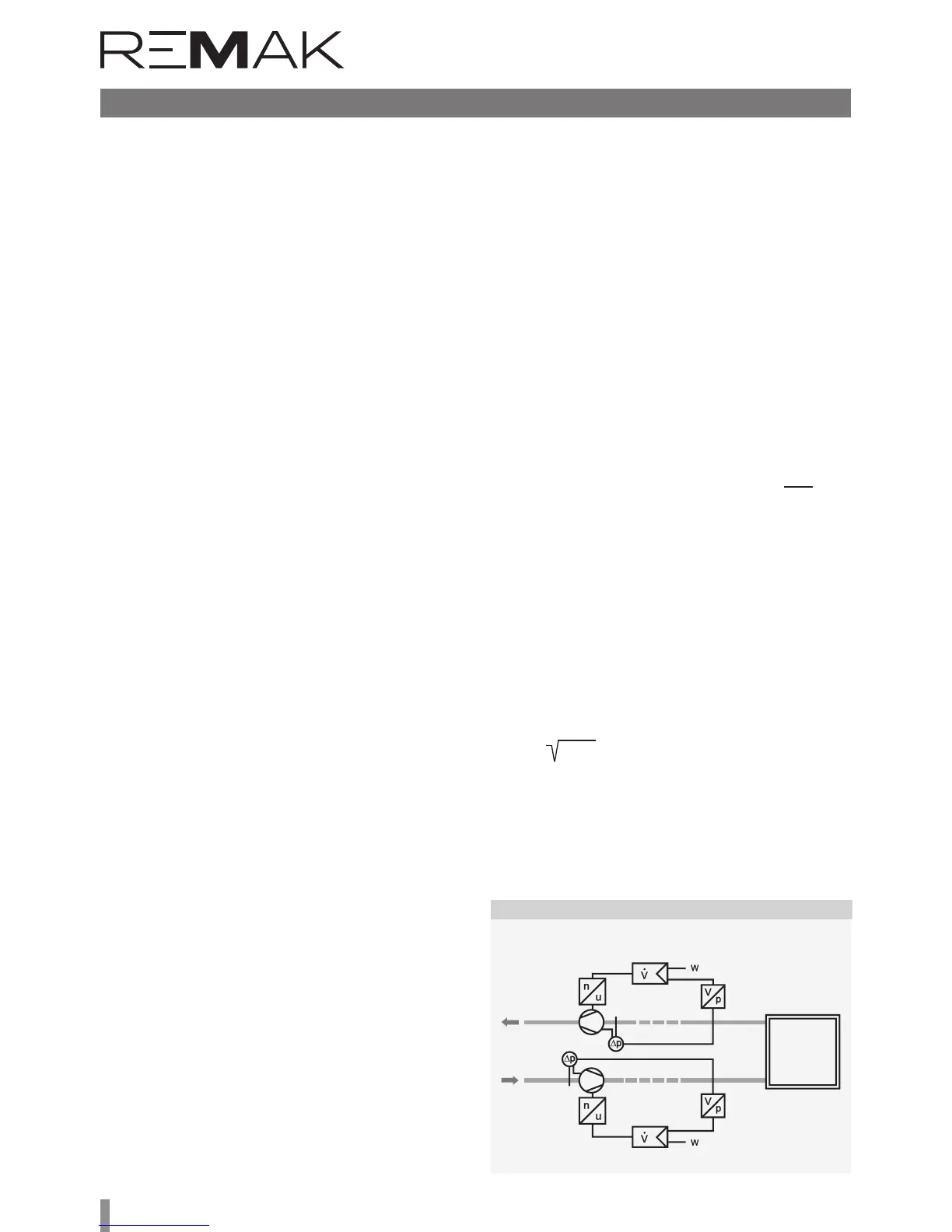
Figure 15 – Constant Pressure Control