15
Control units VCS
Control and Protection Functions
Temperature Required Value Compensation
Temperature compensation is actually a correction (shi) of
the required value (set point) of the controlled (room) tempera-
ture according to the outdoor temperature sensor reading,
which adjusts (in addition to other correction values) the
temperature specified in the temperature mode settings. It is
mainly used to reduce differences between outdoor and indoor
temperatures (to eliminate thermal shocks) and the energy
demand of device operation. On the other hand, it can increase
differences ("aggressiveness") in control, if adjusted reversely.
Note: e data point values on the controller are described in
full text (not using abbreviations like TH1, TC1, etc.). Generally,
minus control is also possible.
Fan Speed Compensation
e VCS control unit system enables the pre-set fan speed
to be adjusted depending on the air temperature, air quality
or mixing damper position using fan speed compensations.
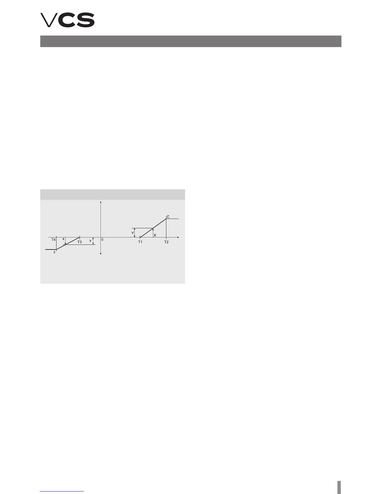
T3 .....Starting point for heating compensation
T4 .....End point for heating compensation
c ........Max. compensation value (delta T)
x.........Actual outdoor temperature
y.........Actual fan speed shi for heating
the supply air temperature and comparing it with the required
supply air temperature and then followed by fan output
compensation. e compensation will be activated if the
difference between the required supply air temperature and
the actual supply air temperature is greater than the pre-set
temperature hysteresis. e actual correction extent is related
to the settings of the PID controller constants.
n Heating Compensation: It reduces the fan output and
thus sufficient supply air heating is achieved based on the
smaller air volume (used to eliminate insufficient output of
the heat exchanger).
n Cooling Compensation: It increases the fan output (higher
air-flow rate) and thus makes the room environment more
comfortable, if cooling is insufficient.
is type of compensation also enables a change to the priority
cooling – fan. So the change in the fan speed is applied first
and then active cooling is applied as the request for cooling is
rising. e settings can be performed using the HMI controller,
refer to the chapter Additional Operating Mode and Function
Setting Options.
Air Quality-Dependent Fan Speed Compensation
e fan output can be adjusted depending on the measured
CO
2
(VOC, CO) content and the pre-set required value. If the
CO
2
(VOC, CO) content is higher than the pre-set (permissible)
value, the fan speed will be increased. e compensation ex-
tent is affected by the settings of the PID controller constants.
e measured value range must be set depending on the sen-
sor used. Further, the sensor characteristic (Normal ascending
for CO
2
and VOC or Inverse descending for CO) must be set.
For the settings, refer to the Data Points.
Air Quality-Dependent Damper Position
Compensation
Functionality is similar and the settings are common with the
air quality-dependent fan speed compensation. e fan output
or mixing damper position can be affected by the difference
between the measured and pre-set required CO
2
(VOC, CO)
concentration in the room. e volume of fresh air will be
increased if the measured value is higher than the required
value. e volume of circulated air will be decreased. e
compensation extent is affected by the settings of the PID
controller constants.
Humidity-dependent Damper Position Compensation
If dehumidification using cooling is not sufficient (or not
available), humidity-dependent mixing damper position com-
pensation is the next step. is is adjusted depending on the
required humidity and measured humidity in the room. If the
measured humidity is higher than the required humidity in the
room, the compensation will be activated.
Humidity-dependent Fan Speed Compensation
e fan output is controlled depending on the required hu-
midity and measured humidity in the room. If the measured
humidity is higher than the required humidity in the room, the
compensation will be activated. e compensation function
can either be set to increase or reduce the fan output.
e compensation functions can be enabled using the HMI
controller, refer to the chapter Additional Operating Mode
and Function Setting Options.
e sum of individual compensations creates a so-called total
compensation which affects the fan speed change.
Outdoor Temperature-Dependent Fan Speed
Compensation
e compensation adjusts the fan speed in regards to high
or low outdoor temperatures. e fan speed is adjusted de-
pending on the maximum heating or cooling compensation
settings. A positive compensation value represents a fan
speed increase. A negative compensation value represents
a fan speed reduction.
Note: To make the compensation effective, it is necessary
to set a suitable maximum compensation value if only one
compensation is used.
Room (Outlet) Temperature-Dependent Fan Speed
Compensation
e fan output is adjusted depending on the required room
temperature and the measured room (supply air) tempera-
ture. e compensation will be activated if the measured
temperature is lower than the required temperature. Using
the compensation function, the fan speed can either be
increased or reduced.
Heating/Cooling-Dependent Fan Speed Compensation
e request for heating or cooling is evaluated by measuring
T1 .....Starting point for cooling compensation
T2 .....End point for cooling compensation
C ........Compensation value (delta T)
X ........Actual outdoor temperature
Y ........Actual fan speed shi for cooling
delta speed (%)
Outdoor temperature (°C)
Heating Compensation Settings
(Winter)
Cooling compensation settings
(summer)
Figure 14 – Fan Speed Compensation Description