9
Control units VCS
Control and Protection Functions
Wiring
n A shielded conductor must be used for the Modbus bus
connection. e maximum conductor length depends on
the communication speed. A maximum length of approx.
1000 m is recommended for the baud rate of 9600 Bd. e
recommended conductors are included in the documentation
created by the AeroCAD design program.
n e controller is connected to two terminals marked A+
and B- and to the REF signal detection reference voltage
terminal, which must always be interconnected with other
participants on the bus.
n To ensure correct functioning of the bus, the fi rst and last
device on the bus must be fi tted with a terminal resistor. e
fi rst device, i.e. the master controller, terminal resistor setting
is performed using the so ware (ensured by REMAK in the
factory). e last device terminal resistor setting is performed
on the last frequency inverter in the line connection. Refer to
the Modbus bus wiring diagram. e setting procedure of
the last terminal resistor is described in the documentation
for a corresponding frequency inverter. A 120 Ohm resistor
connected between the communication can also be used to
terminate the wiring.
Fan Failure Detection
n To detect any fan failure, the motor thermo-contact and
diff erential pressure sensor are connected to the frequency
inverter inputs. e information provided by these elements
is transmitted through the Modbus communication line to the
control system, where it is processed.
Modbus RTU Communication Settings
n Each frequency inverter connected to the bus must be
assigned a unique address as defi ned in the control system
data points.
Pre-set Frequency Inverter Addresses – ModBus:
Inlet Fan
Inlet fan address =1
Backup or twin fan address =2
Backup twin fan 1 address =3
Backup twin fan 2 address =4
Outlet fan
Outlet fan address =5
Backup or twin fan address =6
Backup twin fan 1 address =7
Backup twin fan 2 address =8
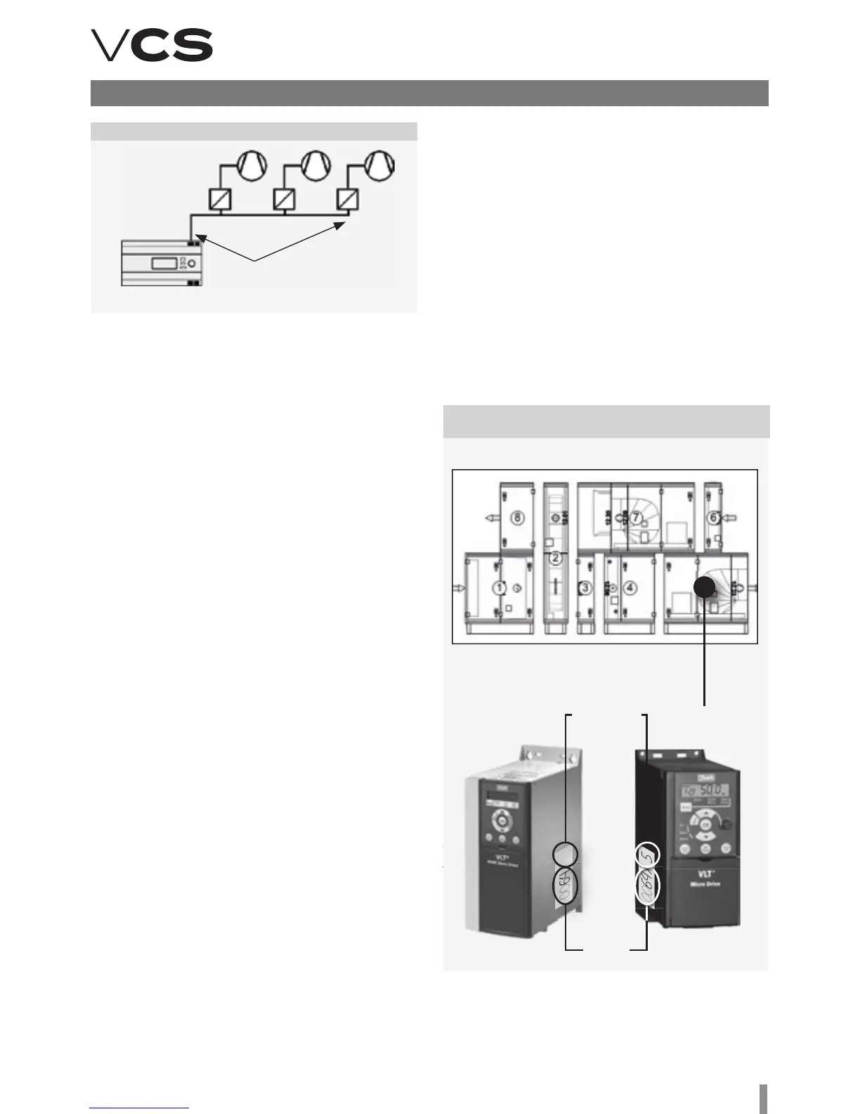
Figure 10 – Inverter connection to the Modbus RTU
Figure 11 – Inverter association with a corresponding
section
terminal
resistor
RS485
FM1
Master
controller
FM2 FM3
Warning
e frequency inverter association cannot be exchanged
between diff erent sections! For information about frequency
inverter association with a corresponding section, refer to
the fi gure.
Auxiliary Fan
Auxiliary fan address =9
Twin fan address =10
Rotary Heat Regenerator
RHR motor address =11
n e data points of all frequency inverters for communica-
tion with the Modbus bus must be set in accordance with the
VCS control unit:
• Baud rate (9600 Bd – pre-set)
• Parity (none – pre-set)
• Number of stop bits (2 stop bits – pre-set)
• Response time limit
• Number of data bits (as standard, 8 bits – pre-set)
All data points for the used frequency inverters are available
on our website: www.remak.eu
Corresponding
section number
Order
number
5