69
Control units VCS
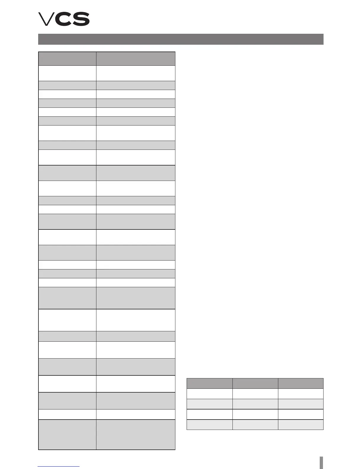
Failure name Failure Description
List of failures (HMI-DM...)
BackdraProtec Gas heater thermostat
switching ON
Burner Gas heater
ElectricPreheating Electric pre-heating
ExtraElectricalHtg Electric aer-heating
CondensingUnit Condensing unit
FreqInvRotHeatEx ROV failure
AntiFreezeHeatEx Heat exchanger
antifreeze protection
SplyFanMainTK Main inlet fan - ermocontact
SplyFanBckUpTK Backup inlet fan -
ermocontact
SplyFanMainDifPr Main inlet fan - pressure
deference sensor
SplyFanBckUpDifPr Backup inlet fan - pressure
deference sensor
SupplyFanBack-up Active inlet fan twin backup
ExhFanMainTK Main outlet fan - ermocontact
ExhFanBckUpTK Backup outlet fan -
ermocontact
ExhFanMainDifPr Main outlet fan - pressure
deference sensor
ExhFanBckUpDifPr Backup outlet fan - pressure
deference sensor
ExhaustFanBack-up Active outlet fan twin backup
CommunicatioModbus Modbus communication
FanOperHours Fan operating hours
StptSplyTmpDev Difference between
required and inlet air
temperature monitoring.
StptRoomTmpDev Difference between required
and room (outlet) air
temperature monitoring.
HeatPumpDefrost Heat pump defrosting function
Inlet Pressure Unconnected or damaged
pressure sensor - inlet fan
Outlet Pressure Unconnected or damaged
pressure sensor - outlet fan
Inlet Air Flow Unconnected or damaged flow
sensor - inlet fan
Outlet Air Flow Unconnected or damaged flow
sensor - outlet fan
Humidifier Humidifier fault
Reduced
humidification output
Reduced humidification output
due to the temperature priority
(swimming-pool unit) – an
information message
Operating mode 1st contact 2nd contact
Auto Off Off
Lower stage On Off
Higher stage Off On
Stop On On
Setting of the Run operating state (temperature mode and fan output stage) and timer
(only for one specific device) is performed using the HMI-SG controller in the List of
Data Points in the section Settings – External Devices.
Other Ways of Control
External control
is enables the control unit to be connected to other technology
using single- or two-contact control. e Auto operating state
of the air-handling unit is always the default state for external
control.
Single-Contact Control
is type of control can be performed in two ways (Start (default)
or Start and Stop functions) depending on the data point setting.
Start function: By activating the switch (switching 1/0), the
air-handling unit is put into the Run operating state (fan output
stage and temperature mode). e control unit time in the Run
state is always given by the timer settings. Another activation of
the switch will prolong the control unit time in the Run state for
a pre-set time in the timer. Once the pre-set time has elapsed,
the unit will go into the Auto operating state. If the timer is set
to zero, the contact input is ready for the switch action (on-off,
switching 1) – if the switch is in the "On" position, the air-handling
unit is in the Run operating state; aer switching to the "Off"
position, the air-handling unit will go into the Auto state.
Start and Stop function: By activating the switch "Start
function" (switching 1/0), the air-handling unit is put into the Run
operating state (fan output stage and temperature mode) for
the timing period. Upon activation of the switch "Stop function"
in the active timing interval, the pre-set operating mode will be
stopped and the unit will go into the Auto state. e air-handling
unit will also go into the Auto state once the timing interval has
elapsed. If the timer is set to zero, the contact input is ready for
the switch action (on-off, switching 1) – if the switch is in the
"On" position, the air-handling unit is in the Run operating state;
aer switching to the "Off" position, the air-handling unit will go
into the Auto state.
Two-Contact Control
is enables the selection of two Run mode operating states
(Higher and Lower). Each Run operating state is set in a different
temperature mode and fan speed stage. By combining the Stop
or Auto operating modes, it is possible to set the required state
of the Run mode. e contact states can be combined as follows:
Remote Signalling
e VCS Control unit can optionally be equipped
with one or two outputs for remote signalling.
Depending on the configuration, the following:
n Only failure (non-potential contact, max. load 230 V/1 A)
n Failure and operation (2 non-potential contacts, max. load
230 V/1 A).