44
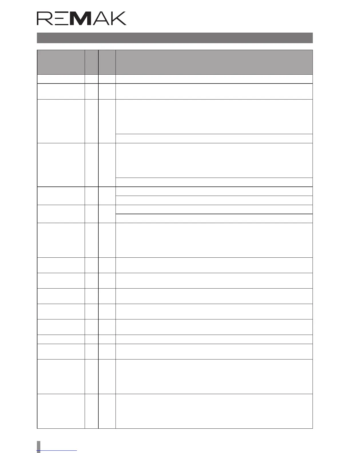
List of Failures (HMI-SG controller)
Failure
Description
Class
Failure
Number
Failure Causes
Reduced humidifi-
cation output
B 10
Reduced humidification output due to the temperature priority (swimming-pool unit)
– an information message.
Auxiliary Fan B 15
1.) Communication error between control unit and the auxiliary fan frequency inverter
(Modbus data bus) – inverter internal error; wrong settings of the frequency inverter data
points – bus communication protocol, data transfer rate, parity, number of stop-bits, com-
munication timeout; poor connection of the bus cable to the frequency inverter terminals;
bus terminal resistance settings on the last frequency inverter has not been performed.
2.) Auxiliary fan failure (Modbus data bus) - thermo-contact, flow sensor
Auxiliary Fan - twin B 16
1.) Communication error between control unit and the auxiliary fan twin frequency inverter
(Modbus data bus) – inverter internal error; wrong settings of the frequency inverter data
points - bus communication protocol, data transfer rate, parity, number of stop-bits, com-
munication timeout; poor connection of the bus cable to the frequency inverter terminals;
bus terminal resistance settings on the last frequency inverter has not been performed.
2.) Auxiliary fan twin failure (Modbus data bus) - thermo-contact, flow sensor
Backup fans
in the inlet
B 18
Main inlet fan failure (backup fan activated) - thermo-contact, flow sensor
A Class failure – inlet backup fan shutdown
Backup fans
in the outlet
B 19
Main outlet fan failure (backup fan activated) - thermo-contact, flow sensor
A Class failure - outlet backup fan shutdown
Communica-
tion, Modbus
B 23
Communication error between control unit and the fan or ROV frequency inverter (Modbus
data bus) - inverter internal error; wrong settings of the frequency inverter data points
– bus communication protocol, data transfer rate, parity, number of stop-bits, commu-
nication timeout; poor connection of the bus cable to the frequency inverter terminals;
bus terminal resistance settings on the last frequency inverter has not been performed.
Process com-
munication KNX
B 23 Communication error between control unit and HMI-SG controller (KNX bus)
Room unit 1 -
Temperature
B 24 Disconnected or damaged HMI-SG1 controller
Room unit 2 -
Temperature
B 24 1) Disconnected or damaged HMI-SG2 controller
2) Wrong HMI-SG2 controller communication address setting (the same address with
the HMI-SG1 controller)
Outdoor tem-
perature
B 25 Disconnected or damaged outdoor temperature sensor
Room temperature B 26 Disconnected or damaged room temperature sensor
Outlet tem-
perature
B 28 Disconnected or damaged outlet temperature sensor
Inlet temperature
difference
B 32
Information message on the difference between inlet and required temperatures, provid-
ing the Inlet and Required Temperature Difference Monitoring has been activated (in the
data point 201). If the temperature difference is higher than pre-set Maximum Difference
(data point 801) or if the inlet temperature drops below the pre-set minimum threshold
(data point 803), an information message is displayed.
Room tempera-
ture difference
B 33
Information message on the difference between room/outlet and required temperatures,
providing the Inlet and Required Temperature Difference Monitoring has been activated
(in the data point 201). If the temperature difference is higher than pre-set Maximum
Difference (data point 807) or if the room/outlet temperature drops below the pre-set
minimum threshold (data point 809), an information message is displayed.