4
Design
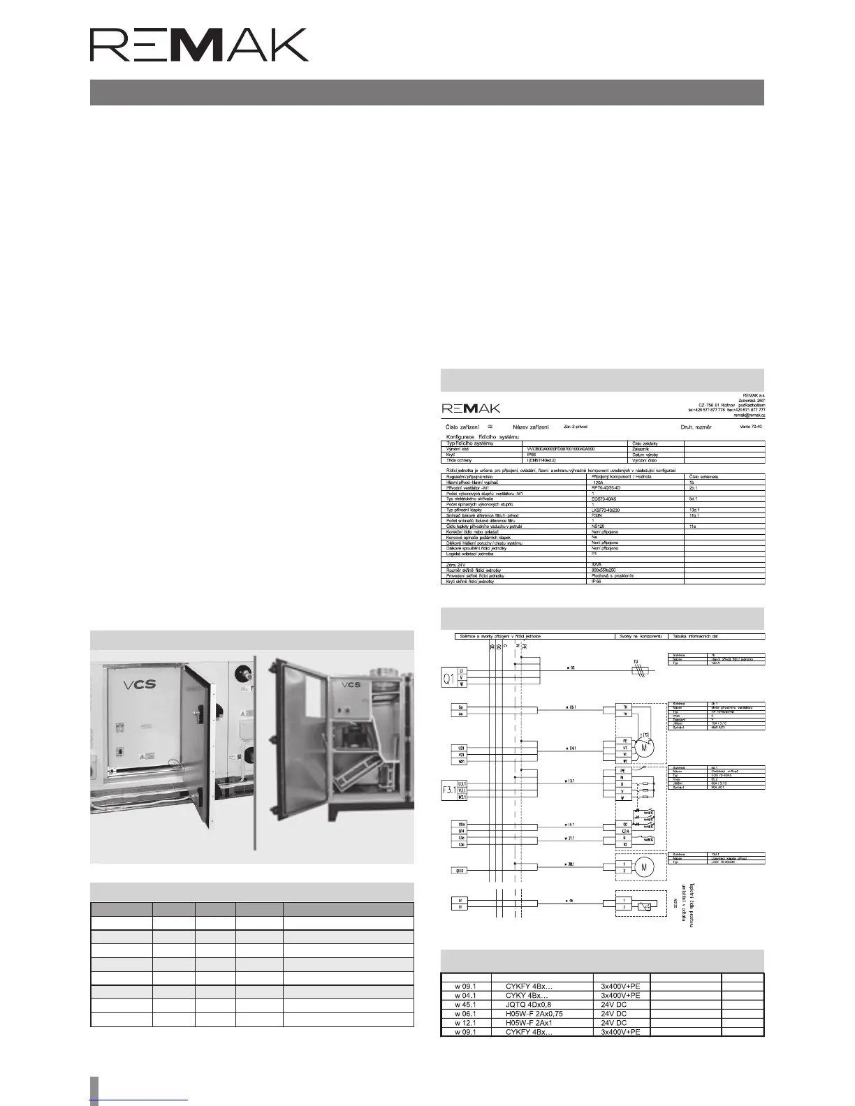
Table 2 – List of connecting cables (example)
Cable No.
Figure 7 – Component wiring (example)
Figure 6 – Summary of connected components (example)
Boxes
Indoor VCS control units are built into plastic or sheet metal
cabinets with front transparent doors under which controls
are located. e permissible ambient temperature is 0 ° C
to + 40 ° C.
VCS in exterior design are built into sheet metal cabinets
with full front doors under which controls are located. In
the confi guration so ware we can design: range of average
temperatures -40 ° C to 35 ° C, cabinet mounting (hanging /
stand), door design (le / right), lighting, service drawer (select
according to customer's destination).
A space of minimum 15 cm must be le on each side of the
box to allow access for cooling air and for changing the fi lter
which is fi tted in front of the fan.
As a standard, we provide a door lock and a box for storing
unit documents. Depending on the particular confi guration of
the control unit, these enclosure dimensions are used (Table
1). e electrical enclosure of the plastic case corresponds to
IP 65 with the door closed and IP 40 when the door is open.
e electrical cabinet cover is IP 55 or IP 66 (depending on
enclosure type) when the door is closed and IP 20 when the
door is open. e metal enclosure with additional ventilation
is IP54 with the door closed and IP 20 with the door open.
The VCS control units can be mounted directly on the
Flammability Levels A and B according to EN 13501-1.
Additionally, the VCS control unit can be manufactured in an
integrated design as part of the ventilation unit section. One
of the options is a built-in section for assembled VZTs, which
includes adjustments for the environment. is section is used
when designing VZT with IP44 protection as well
for outdoor units (with heating or cooling of the control unit).
Table 1 – box dimensions in mm
If needed, the boxes, sized 2000 × 800 × 400 mm and 2000 × 1000 × 400 mm, can be
fi tted with a ventilation set – a fan and a louver in opposite corners.
VCS
ACX36/RMK
Figure 5 – Installation in the XP unit section
Design
e control system design is based on the selection of re-
quired features and on its internal confi guration. e design
is performed automatically using the algorithm integrated
into the design so ware also used for the air-handling unit
design. e design output provides an exact specifi cation of
the control unit, including the following individualised lists for
a specifi c device:
n Summary of connected components
n Wiring diagrams of all components
n List of all recommended cables for the connection of all
components (the cables must always be used in accord-
ance with the electrical equipment project documenta-
tion).
Version Height Width Depth Usual application
Plastic 610 340 160
Vento, FP, some XP (single-speed)
Plastic 610 448 160
Vento, FP, some XP (single-speed)
Plastic 842 448 160
Vento, FP, some XP (single-speed)
Sheet-steel 800 550 250 XP, sophisticated Vento assemblies
Sheet-steel 1200 750 300 XP
Sheet-steel 1600 750 300 XP
Sheet-steel 2000 800 400 XP
Sheet-steel 2000 1000 400 XP
(Recommended) cable type Power Supply Cable length Note
a) AeroMaster XP b) CAKE