17
Control units VCS
Basic Information on VCS
Operating Modes
Operating states
ere are three operating states defined for VCS control units
(Stop, Run, Auto):
Stop – e device is in standstill mode (fans stopped). Impor-
tant safety features like antifreeze protection and moderate
pre-heating of the water heater are retained.
Run – e device is started in accordance with the pre–set
temperature mode and fan speed.
Auto – Control is switched to the next operating mode with
a lower priority. e Auto operating state cannot be set in
the time schedule mode because it is a control type with the
lowest priority.
e operating mode determines which operating state will be
active according to priorities (see Operating Modes).
Operating Modes
e control unit’s operating state (i.e. whether the air-handling
unit is in the Stop or Run state) is determined by one of the
operating modes (manual control, external control, HMI-SG
controller, BMS or time schedule modes). HMI-DM or HMI-TM
controllers affect control in the manual control mode. External
control is performed by single- or two-contact control. BMS
control enables control of the control unit by the higher level
control device (e.g. smart building control systems; Note:
pending). To control air handling systems, the HMI-SG control-
ler is connected to the control unit.
e operating mode which will determine the device’s oper-
ating state (Run or Stop) is determined by the priority. Each
operating mode is assigned a priority, i.e. the first option to
control the control unit, to eliminate mutual interference. e
operating modes are prioritized as follows, from the lowest
to highest priority:
n Manual control
n External control
n Local HMI-SG controller
n BMS (pending)
n Time schedule
n Additional operating modes
e priorities and entire control system are shown in the
diagram on the following page.
Control and Protection Functions
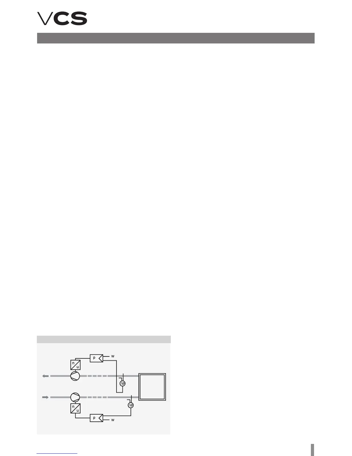
Figure 16 – Constant pressure control
Constant pressure control
Fan speed is controlled depending on the desired air pressure
(Pa). e air pressure is measured by a sensor; the control
system evaluates this value and compares it with the required
value. e resulting fan speed is controlled so that the required
air pressure will be reached at the point of measurement.
It is necessary to set the following air flow sensor param-
eters (see the Sensor Operating Manual):
n Mode (for CPG = Mode 4.00)
n Measuring range: As needed (200 Pa, příp. 1000 Pa)
It is necessary to set the following parameters of the VCS
control Unit (see List of HMI Data Points):
n Air pressure sensor measuring range – (maximum value
from the CPG air pressure sensor in Pa)
n Required values (separately for the inlet and out-
let fans). 5 required values are available for selection.
Constant Air Flow + Overpressure in the Room Control
e inlet branch (fan) is adjusted to the constant air flow so
that the required air volume is delivered to the room. e outlet
branch is adjusted to the required difference in overpressure in
the room. us, the outlet fan is adjusted to the required pres-
sure (overpressure) depending on the pressure sensor location.
Application: Preventing dirt from entering the room.
Constant Air Flow + Underpressure in the Room Control
e outlet branch (fan) is adjusted to the constant air flow.
e inlet branch (fan) is adjusted to the difference in under-
pressure in the room. us, the inlet fan is adjusted to the
required pressure (underpressure) depending on the pressure
sensor location.
Application: Preventing dirty air from entering the adjacent
rooms
Note: When commissioning the system, it is necessary to
perform the settings and regulation of the device (PID con-
stants, FI ramp, etc.)
n Number of fans (for twins = 2). e air flow rate of one fan
is measured and is then multiplied by the number of fans.
n Required values (separately for the inlet and outlet fans)
5 required values are available for selection.