HMI-SG controller enables the following items to be
reviewed:
n Room (outlet) temperature
n Current air-conditioning process (cooling, heat recovery,
mixing or heating)
n Temperature mode (Economy, Comfort)
n Current system time and day of the week
n Fan output stage
Other information is available via the List of Data Points, see
the chapter Data Point List Access and Editing. e HMI-SG
POL822.60/STD hand controller is used to control air-
handling devices. is controller can be connected to the POL
4xx or POL 6xx master controller (respective to the terminals
ready in the control unit).
Operating conditions
Degree of protection: IP 30 Permissible ambient temperature:
5 °C to 40 °C Relative humidity < 85%
Warning:
To avoid unintentional unit start-up, the master switch must be
switched off and locked when repairing the VCS unit.
Wiring and Installation
e HMI-SG controller is connected to the Process Bus (KNX).
A twin cable or a twisted pair of leads can be used to perform
the connection to the KNX bus.
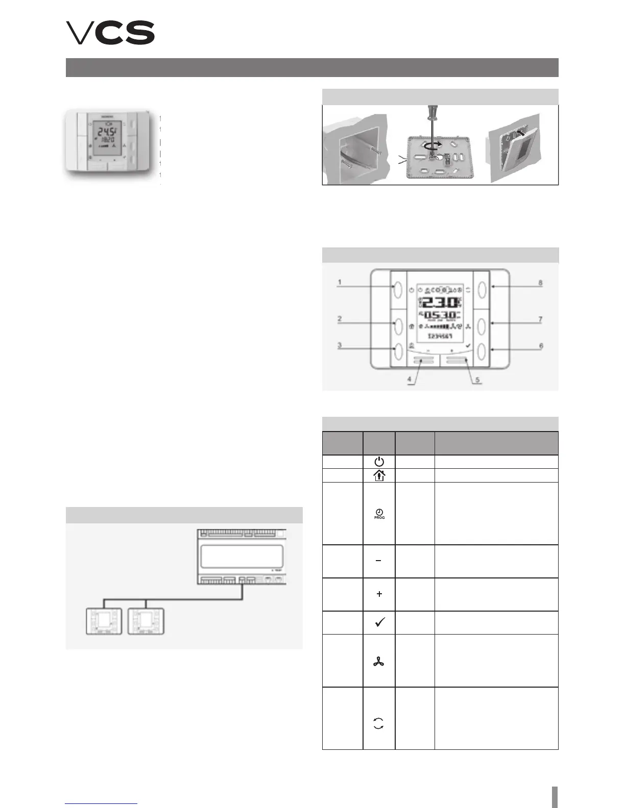
Function Buttons
e room unit consists of the face plate and back cover,
which can be separated. ere are 8 function buttons on the
controller's face plate.
Figure 14 – Connection to the control unit
Figure 19 – HMI-SG controller
Controller Description
Table 3 – Function Buttons description
Button
number
Icon Name Function description
T1 Power Air-handling unit start or stop
T2 Presence not used
T3 Program
e time schedule button: by
holding this button, you can
set the date; by pressing this
button, you can set the desired
temperature mode timing and
required fan output stage
T4 Minus
Temperature correction –
pre-set depending on the
selected temperature mode
T5 Plus
Temperature correction –
pre-set depending on the
selected temperature mode
T6 OK
Confirmation of the date or time
schedule settings
T7 Fan
Fan output (speed) stage setting;
each button cyclically increases
the setting by one stage. e cur-
rent output stage is displayed on
the display
T8 Mode
Temperature mode selection
(Auto, Comfort and Economy). By
pressing the button, the modes
can be cycled. e currently
selected temperature mode is
indicated by an icon on the display
Master
controller
Process Bus
HMI-SG 1 HMI-SG 2
Local HMI-SG controller
Figure 18 – Wiring box installation
e controller can be installed using a wall wiring box or
embedded in plaster. e maximum distance between the
control unit and room controller is up to 700 m.
HMI-SG controllers are connected to the master controller in
series and wiring is always performed to one point.
Note: e Installation Instructions are part of the HMI-SG
controller delivery.