23
Control units VCS
Data Point List Access and Editing
An overview of the structure of parameters accessible via the
HMI-SG controller is available in the List of Data Points upon
logging in using the appropriate access right level. e data
points for writing and reading are assigned different access
right levels. e procedure for access for editing and reading
of data points is as follows:
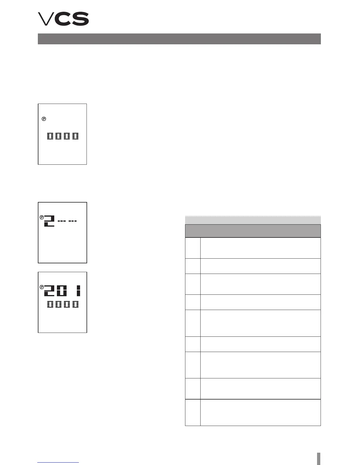
1) e edit mode is signalled by
an icon (I16). is mode can be
accessed by pressing the Plus
(T5), Minus (T4) and Mode (T8)
buttons simultaneously. e cur-
sor flashes in the first position
from the le, ready for the 1st
password digit to be entered.
Change the value of the digit by
pressing the Plus (T5) or Minus
(T4) button and confirm by press-
ing the Mode (T8) button and the cursor will move to the next
position. e password is activated aer entering and confirm-
ing the last digit of the password by pressing the T8 button.
2) Upon entering the correct
password, the data points for
the respective access level (pass-
word) are displayed.
Note: If the entered password is
wrong, "---" will be displayed.
3) Using the Plus (T5) or Minus
(T4) buttons, select the first num-
ber of the data point group and
confirm the selection by pressing
the mode (T8) button. en select
a desired data point within the
group in the same way as the first
number of the data point group.
e number on the first line rep-
resents a data point code while
the number on the second line
represents its value.
4) If the parameter value is highlighted, the data point is only
for reading. If the parameter value flashes, the data point can
be edited in accordance with the access level you logged in at.
5) e value can be edited by the Plus (T5) or Minus (T4) but-
tons. To confirm changes to the value, press the Mode (T8)
button. Upon confirming the changes, the data point cursor
will start to flash, and you can move to the next parameter
in the group. Another group of parameters, i.e. return to a
higher level, can be made by pressing the Power (T1) button.
Note: If no change is made within 1 minute, the data point
editing mode will be exited.
Control (HMI-SG)
Communication Settings
Once the HMI-SG controller has been connected to the control
unit, the communication between both devices will be set
automatically. If two HMI-SG controllers have been connected
to the control unit, it is necessary to set a new address for
one of the controllers. An interface for the communication
settings will be displayed on the controller, and then parameter
#7 must be changed.
1) e interface for the communication settings is displayed
by pressing and holding the Power (T1), Mode (T8), Minus
(T4) and Plus (T5) buttons simultaneously. e cursor flashes
in the first position from the le, ready for the 1st password
digit to be entered. Change the value of the digit by pressing
the Plus or Minus (T4) button and confirm by pressing the
Mode (T8) button and the cursor will move to the next position.
Changes to the parameter settings can only be made by the
ADMINISTRATOR, SERVICE or USER role users.
2) Aer a correct password has been entered, press the
Mode (T8) button to enter the interface for changes to
parameter settings.
3) Use the Plus (T5) or Minus (T4) buttons to browse the
communication parameters. Press the Mode (T8) button
to confirm selection of the desired parameter (parameters
for communication settings are listed in the following table).
Table 6 – Communication settings
Parameter number/Description
001
KNX connection state
• OK – bus communication is OK
• NF – no bus communication
002
Physical address (X.1.1)
X…value range 0 to 15; generated automatically
003
Physical address (1.X.1)
X…value range 0 to 15; generated automatically
004
Physical address (1.1.X)
X…value range 0 to 252; generated automatically
005
Byte (program) address (X.1.1)
X…value range 0–126 (pre-set value is 5)
is value needs to be changed if several master contro-
llers are connected to the KNX bus by several controllers
006
Room (program) address (1.X.1)
X…value range 1 to 14 (pre-set value is 1)
007
Zone (program) address (1.1.X)
X…value range 1 to 15 (pre-set value is 1)
is value must be changed from 1 to 2 if 2 control-
lers are connected to the same master controller.
008
Network failure detection enabled
Network failure detection enabled or disabled;
network failure is indicated by the word "NET".
009
Physical address automatic
assignment (pre-set value is 1)
0…Room unit uses firmly defined physical address
1…automatic generation of the controller's address