48
Control (HMI-DM,HMI-TM controllers)
HMI-DM (HMI-TM) control devices ensure communication
between the VCS control unit and the user. ey are intended
for air-handling device control, handling and service. e HMI
control device can be connected to the POL4xx or POL6xx
controllers. During controller operation, a single HMI control
device can be connected or disconnected and alternatively (in
sequence) used to control multiple control units (controllers).
Connection
e HMI-DM controller can be connected using a serial inter-
face (4-wire, twisted pair) with two RJ45 connectors. e
cable length is 1.5 m (the cable is included in the delivery).
When installed on a wall, the HMI-DM controller can be con-
nected using a shielded 8-wire UTP cable with two RJ45
connectors. e maximum distance is up to 50 m.
e HMI-TM controller can be connected to the control unit
using a 4-wire cable (twisted pair) with one RJ45 connector
and one slim connector. e cable length is 2.5 m (the cable
is included in the delivery).
Warning
A er connecting the controller to the control unit, it is nec-
essary to route the cable through the PG16 grommet. us
degree of protection IP20 is ensured. If a higher level of protec-
tion of the distribution board cas-
ing is required, the grommet will
have to be resealed. An optional
grommet with an RJ 45 connector
can be used to make it easy to con-
nect (disconnect) the HMI control-
ler (an extra order is required, not
included in the standard delivery).
en the RJ45 connector must
be connected to the RJ45 socket
on the controller. For the socket
marking, see the fi gure.
Button
(Name)
Activity Description
Scrolling
knob
Turning
- Selection from the menu
- Selection from the param-
eters or change to a value
Press - Selection/confi rmation
Hold
- When logged in, press and
hold for at least 3 s to go to
the log-in/log-out page.
- When not logged in at any access
level, the log-in page is displayed.
Esc
Press - Cancels the change to
the parameter value
-Returns to the upper level of
the menu/previous page
- Returns to the last active page
before accessing the Pass-
word Administration page
- Returns to the last active page
before accessing the Home
page using the Info button.
Hold - Goes to the Start Menu
Info
Press - Goes to the Main Menu from
the current menu page
- Goes to the Start Menu
page from the Main Menu
Flashing
green
- Air-handling unit start-up sequence
Green light - Air-handling unit operation
Failures
Press - Every time you press this button,
you will cycle through the following
pages → List of Failures → His-
tory of Failures → Alarm Settings
(failure confi rmation and reset)
Flashing
red
- Active unconfi rmed failures
Red light - Active confi rmed failures
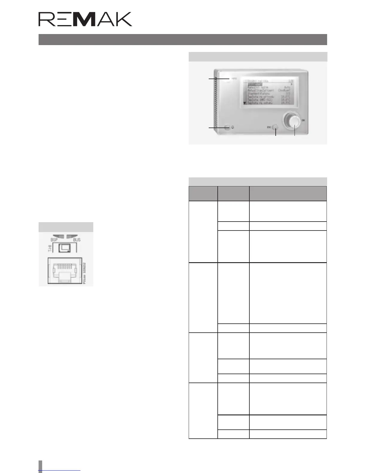
Figure 22
Figure 23 – HMI-DM cotroller
Table 1 – Function Buttons
HMI-DM controller
Operating conditions
Degree of protection: IP 31. Permissible ambient temperature:
-40 °C to 70 °C. Relative humidity <95 %.
Device Description
e controller consists of two separate parts – the face plate
with a display and the rear plate. Dimensions of the HMI-DM
controller are 144x96x26 mm and the integrated LCD display
resolution is 208x96 pixels. e display can show 8 lines. e
HMI-DM controller is equipped with three function buttons,
INFO, FAILURE and ESC, and one scrolling knob. The
scrolling knob and buttons are used to navigate within the
menu and to change the parameters and control values. e
INFO, FAILURE and ESC buttons are equipped with LEDs to
indicate operating states.
e controller can also be delivered in a version for free loca-
tion. e magnets on the rear side of the HMI enable the con-
troller to be attached to metal parts (e.g. the air-handling unit).
Info
Failure
ESC
Scrolling knob
For fi xed mounting, the controller is equipped with threaded
holes on its rear side to screw it to the mounting plate.