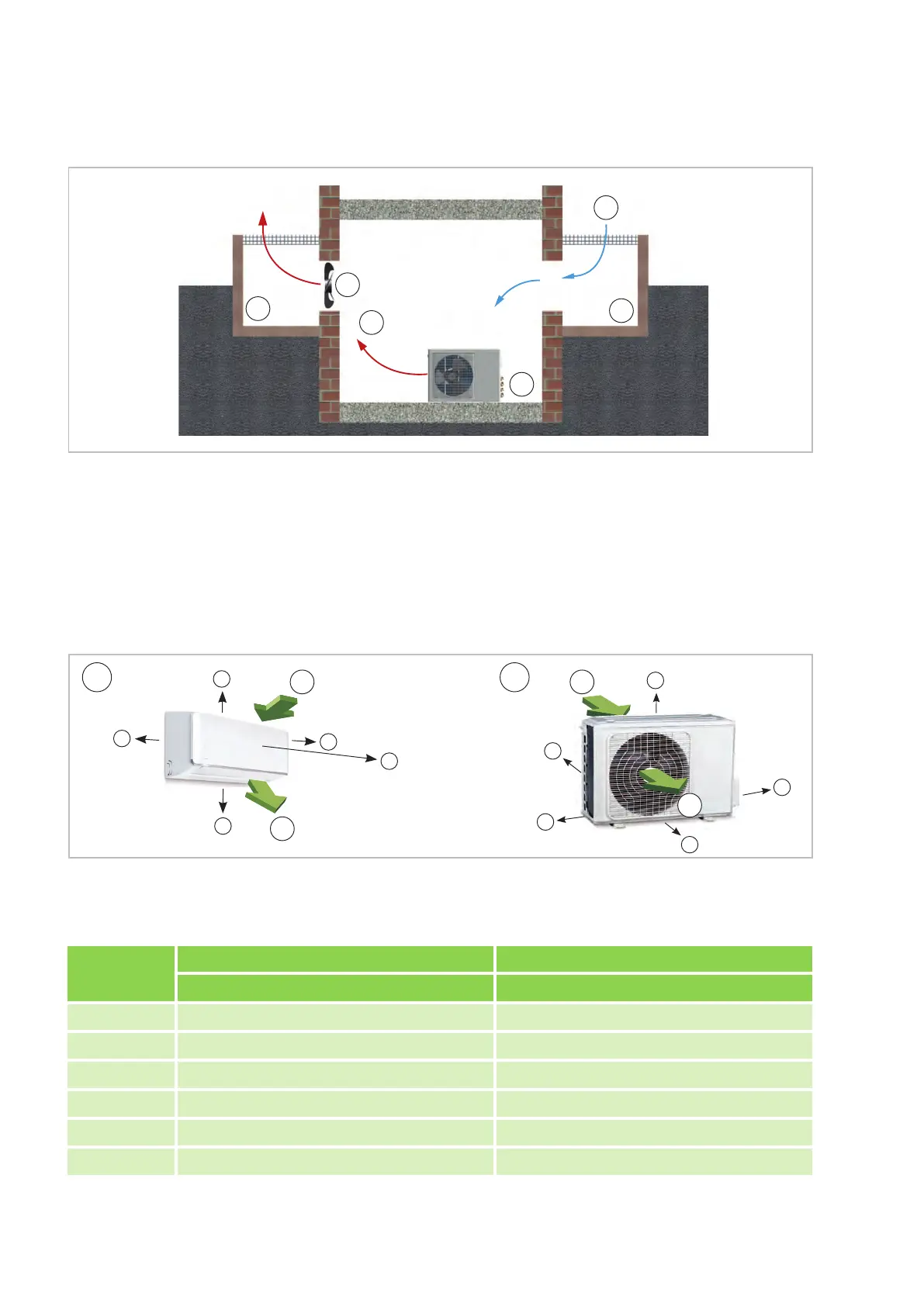
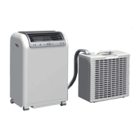
Fig. 23: Installation inside buildings
K: Cold fresh air / W: Warm air
1: Outdoor unit / 2: Additional fan
3: Air shaft
5.5 Minimum clearances
Observe the minimum clearances to allow access for maintenance and repair work and facilitate optimum air
distribution.
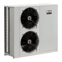
Fig. 24: Minimum clearances of the indoor unit and outdoor unit
AT: Outdoor unit / IT: Indoor unit 1: Air inlet / 2: Air outlet
Measure-
ments (mm)
Indoor units Outdoor units
ML 265 DC-685 DC IT ML 265 DC-685 DC AT
A 120 150
B 1500 700
C 120 400
D - 150
E 120 200
F 1700 -
REMKO ML series
24