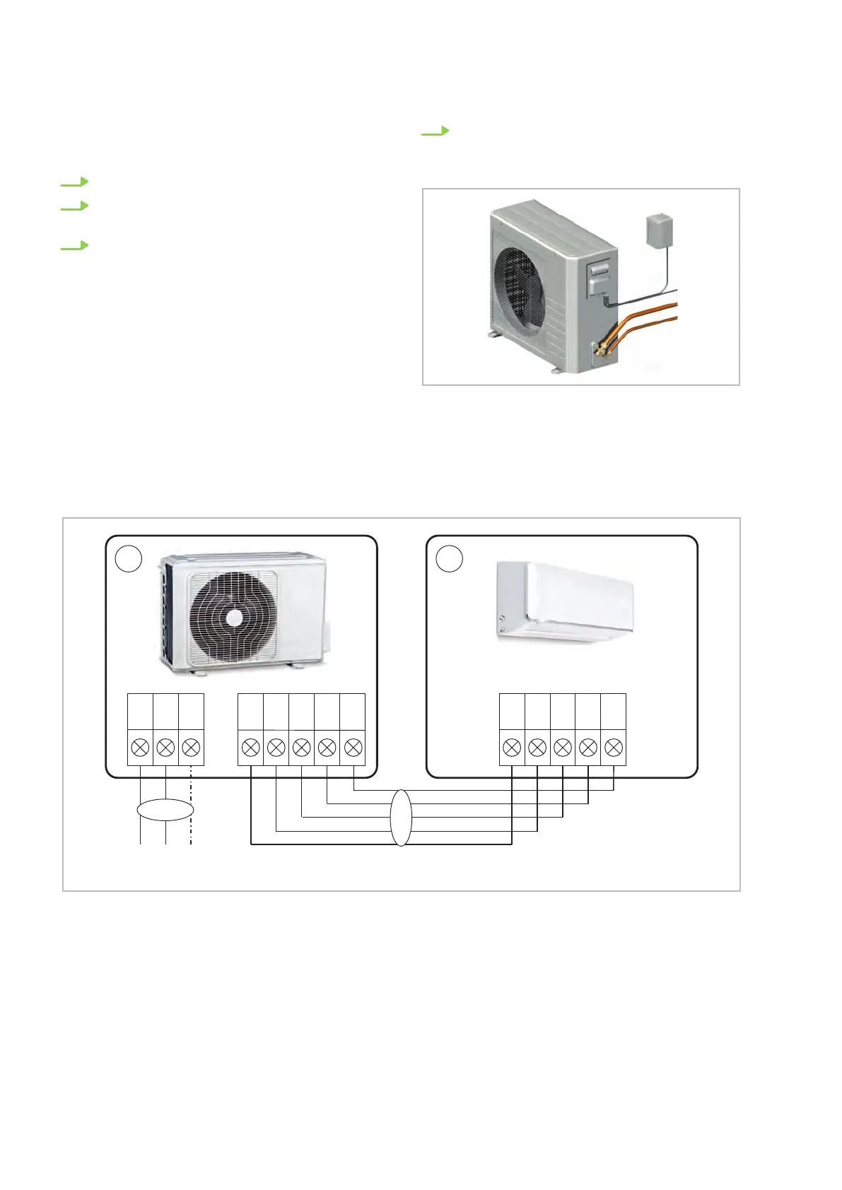
7.3 Connecting the outdoor unit
Proceed as follows to connect the line:
1. Remove the side-panel cover
.
2. Choose a cable-section according to the rele-
vant specifications.
3. Connect the lines as shown on the electrical
connection diagram.
4. Fix the line in the strain relief and re-
assemble the unit.
Fig. 38: Connecting the outdoor unit
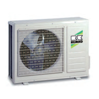
7.4 Electrical wiring diagram
Connection ML 265 DC-685 DC
BA
230V/1~/50 Hz
L N PE W 1(L) 2(N) S 2(N) S PE PE
2
1
W 1(L)
Fig. 39: Electrical wiring diagram
A: Outdoor unit ML 265 DC-685 DC AT
B: Indoor unit ML 265 DC-685 DC IT
1: Power supply cable
2: Communication line
REMKO ML series
34