Outdoor units ML 265 DC-355 DC AT
1 2
3
5
A
B
7
6
C
8
4
W
1(L)
2(N)
S
L
N
CN 1A
CN 60
CN 17 CN 15
CN 31
CN 7
CN 21
CN 50
Blau/Blue
Rot/Red
Schwarz/Black
U
V
W
M
M
Rot/
Red
Blau/
Blue
Yellow or Black/
Gelb oder Schwarz
Braun/
Brown
Yellow and Green/
Gelb und Grün
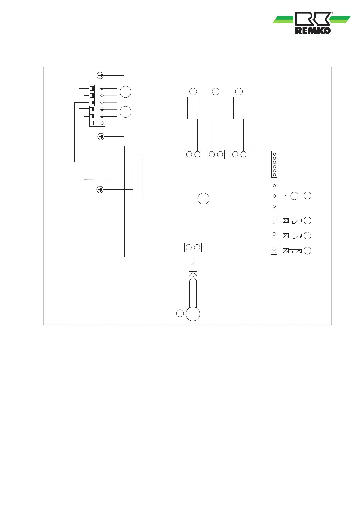
Fig. 42: Electrical drawings
A: Control board
B: Power supply cable
C: Lines to indoor unit
1: Reversing valve
2: Crankcase heating
3: Condensate tray heating
4: Condenser/DC fan
5: Temperature probe for condenser air inlet T4
6: Temperature probe for heat gas line
compressor T5
7: Temperature probe for condenser outlet T3
8: Compressor
37