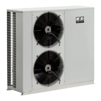
Outdoor unit ML 685 DC AT
2
1
4
3
5
6
7
8
9
10
11
A
1
2
3
Gelb
(Blau)
U
V
W
RY1
CN2
CN7
CN8
Rot
Blau
Schwarz
Weiß
Schwarz
6
Balu
Schwarz
Rot
CN414
Blau
Blau
U
V
W
Y/G
CN6-1
Y/G
Rot
1(L)
2(N)
S
L N
Blau (Schwarz)
L
N
W
3
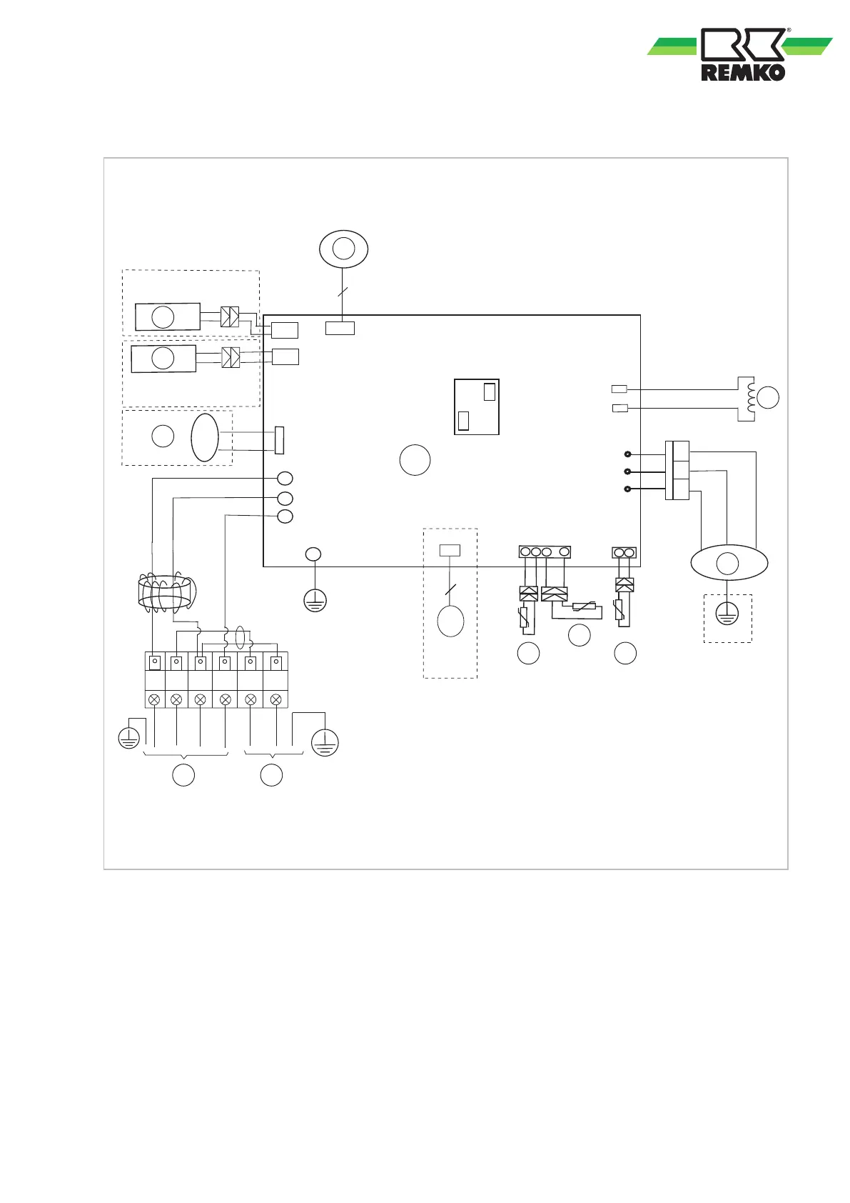
Fig. 44: Electrical drawings
A: Control board
1: Supply line to the indoor unit
2: Power supply cable
3: 4-way valve (optional)
4: Crankcase heating (optional)
5: Condensate tray heating (optional)
6: Fan motor (optional)
7: Transformer
8: Compressor
9: Heat gas probe
10: Condenser temperature probe
11: Temperature probe for condenser outlet
39