Renesas RA Family EK-RA4M2 v1 – User's Manual
R20UT4815EG0100 Rev 1.00 Page 15 of 30
Jan.04.21
To configure the EK-RA4M2 board to use the Debug On-Board mode, configure the jumpers using the
following table.
Table 5. Debug On-Board Jumper Configuration
Target RA MCU MD connected to debug
Target RA MCU RESET# connected to debug RESET#
S124 Debug MCU in normal operation mode
Jumpers on pins 1-2, 3-4, 5-6, 7-8
Target RA MCU debug signals connected to the Debug
Interface
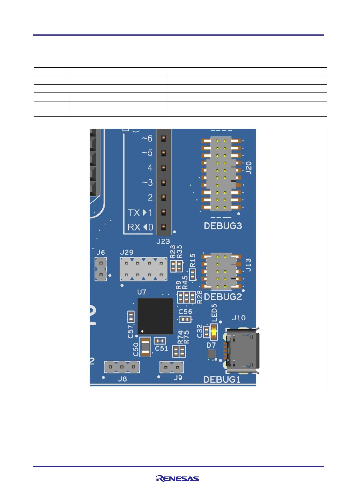
Figure 9. EK-RA4M2 Debug Interface
5.2.2 Debug In
One 20-pin Cortex
®
Debug Connector at J20 supports JTAG, SWD and ETM (TRACE) debug. One 10-pin
Cortex
®
Debug Connector at J13 supports JTAG and SWD. Either of these connectors may be used for
external debug of the target RA MCU.
To configure the EK-RA4M2 board to use the Debug In mode, configure the jumpers using the following
table.