Renesas RA Family EK-RA4M2 v1 – User's Manual
R20UT4815EG0100 Rev 1.00 Page 24 of 30
Jan.04.21
Figure 18. Power LED
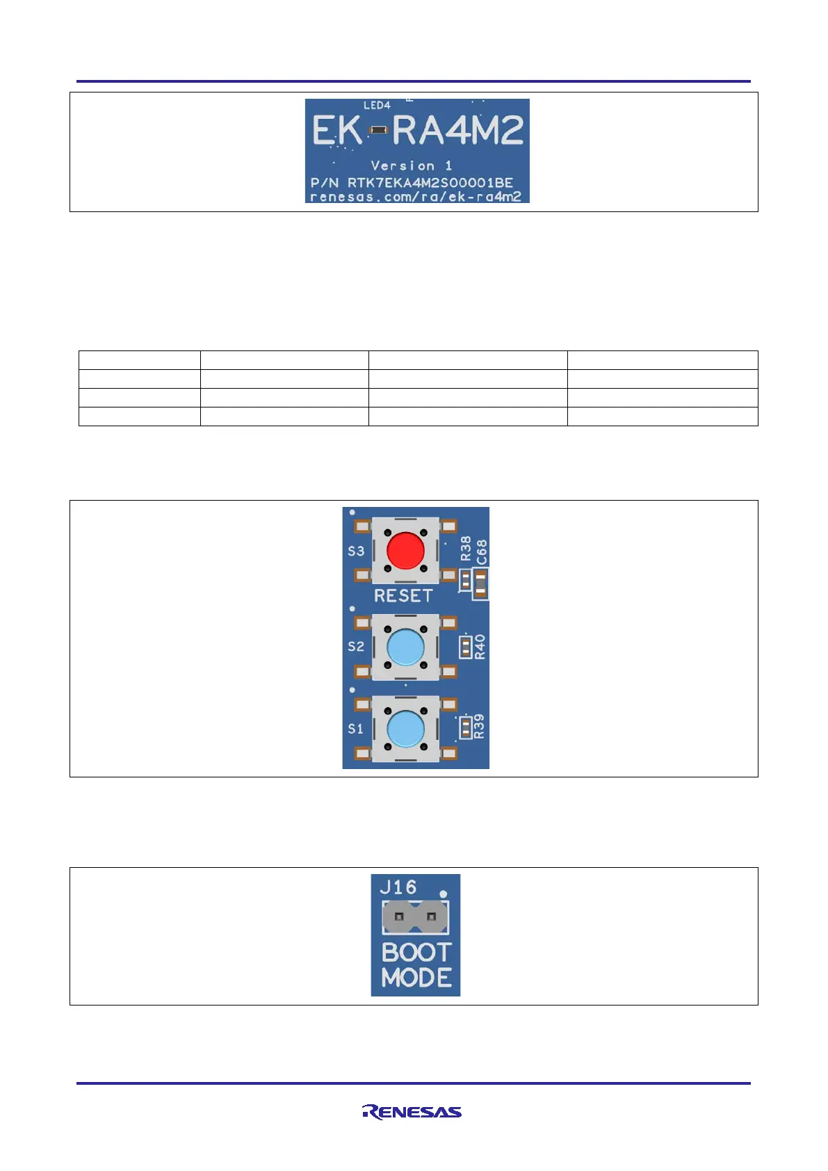
5.5.2 User and Reset Switches
Three miniature, momentary, mechanical push-button type SMT switches are mounted on the EK-RA4M2
board.
Pressing the Reset switch (S3) generates a reset signal to restart the RA MCU.
Table 19. EK-RA4M2 Board Switches
The User Switches S1 and S2 may be isolated from the Main MCU, so the associated ports can be used for
other purposes. To separate S1 from P005, Trace Cut Jumper E31 must be open. To separate S2 from
P006, Trace Cut Jumper E32 must be open.
Figure 19. Reset and User Switches
5.5.3 MCU Boot Mode
A two-pin header (J16) is provided to select the Boot mode (P201) of the RA MCU. For normal operation, or
Single-Chip mode, leave J16 open. To enter SCI Boot mode or USB Boot mode, place a jumper on J16.
Figure 20. Boot Mode
Note: The RA MCU fitted to the EK-RA4M2 board may not contain the latest version of the on-chip boot
firmware.