Renesas RA Family EK-RA4M2 v1 – User's Manual
R20UT4815EG0100 Rev 1.00 Page 23 of 30
Jan.04.21
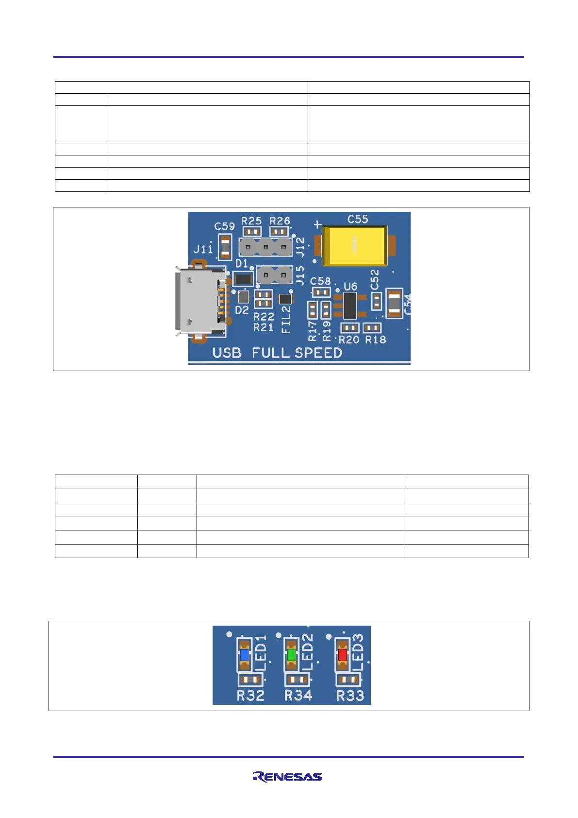
Table 17. USB Full Speed Connector
Host Mode: +5VUSB
Device Mode: P407/USB_VBUS = 2/3 (5VUSB)
USB ID, jack internal switch, cable inserted
Figure 16. USB Full Speed Connector
5.5 Miscellaneous
5.5.1 User and Power LEDs
5 LEDs are provided on the EK-RA4M2 board.
Behavior of the LEDs on the EK-RA4M2 board is described in the following table.
Table 18. EK-RA4M2 Board LED Functions
The User LEDs may be isolated from the Main MCU, so the associated ports can be used for other
purposes. To separate LED1 from P415, Trace Cut Jumper E27 must be open. To separate LED2 from
P404, Trace Cut Jumper E26 must be open. To separate LED3 from P405, Trace Cut Jumper E28 must be
open.
Figure 17. User LEDs