Renesas RA Family EK-RA4M2 v1 – User's Manual
R20UT4815EG0100 Rev 1.00 Page 17 of 30
Jan.04.21
5.2.3 Debug Out
The EK-RA4M2 board can be configured to use the S124 Debug MCU to debug target RA MCU on an
external board.
A yellow indicator, LED5, shows the visual status of the debug interface. When the EK-RA4M2 board is
powered on, and LED5 is blinking, this indicates that the S124 Debug MCU is not connected to a
programming host. When LED5 is on solid, this indicates that the S124 Debug MCU is connected to a
programming interface.
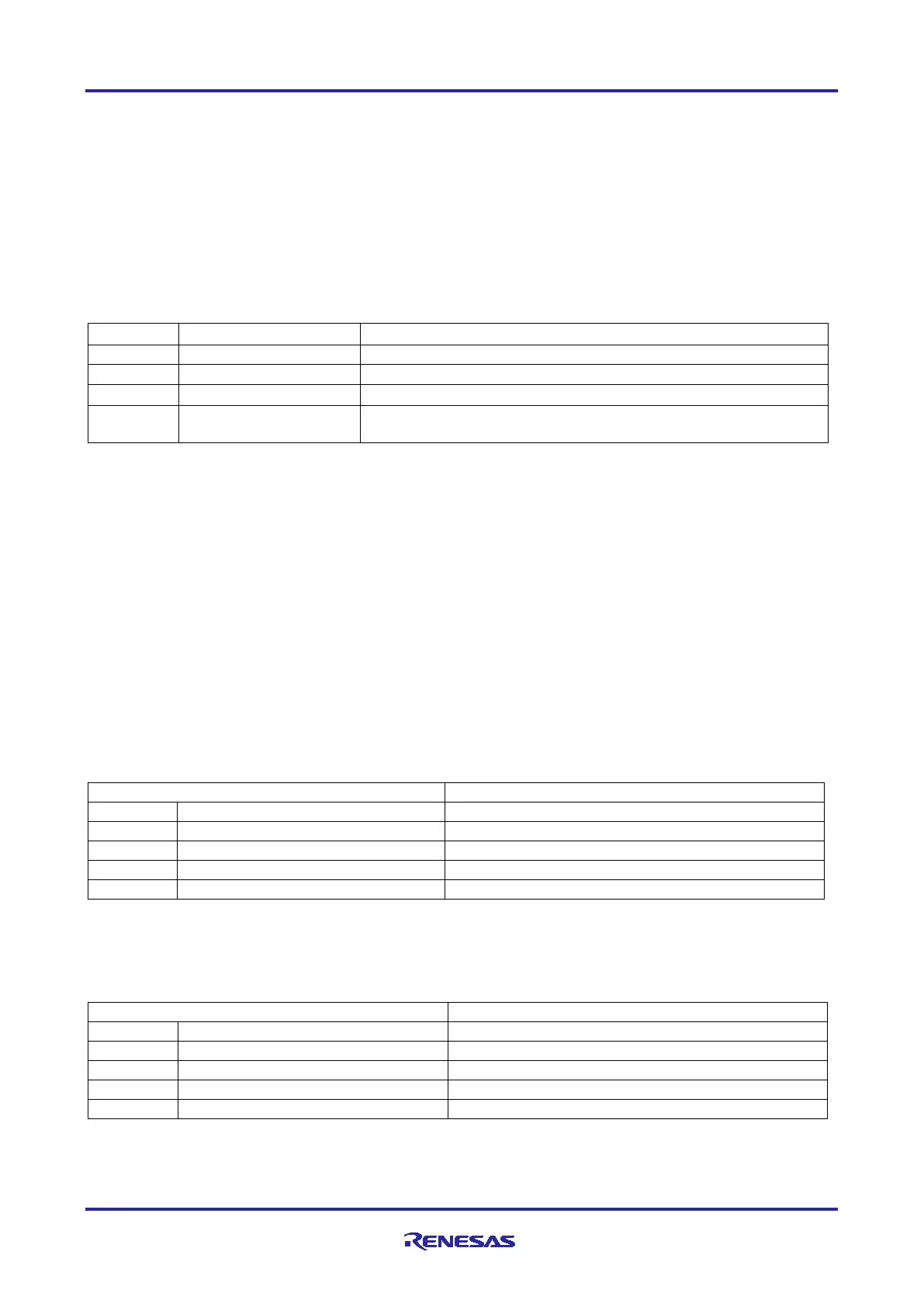
To configure the EK-RA4M2 board to use the Debug Out mode, configure the jumpers according to the
following table.
Table 9. Debug Out Jumper Configuration
On-board RA MCU is held in RESET
S124 Debug MCU in normal operation mode
Disconnects the on-board RA MCU debug signals from the
Debug Interface
5.3 Ecosystem
The System Control and Ecosystem area provides users the option to simultaneously connect several 3
rd
party add-on modules compatible with four most popular ecosystems using the following connectors:
1. Two Seeed Grove
®
system (I2C/Analog) connectors
2. SparkFun
®
Qwiic
®
connector
3. Two Digilent Pmod™ (SPI and UART) connectors
4. Arduino™ (Uno R3) connector
5. MikroElektronika™ mikroBUS connector
5.3.1 Seeed Grove
®
Connectors
5.3.1.1 Grove 1
A Seeed Grove I2C connector is provided at J27. The RA MCU acts as a two-wire serial master, and a
connected module acts as a two-wire serial slave.
Table 10. Grove 1 Connector
5.3.1.2 Grove 2
A Seeed Grove Analog connector is provided at J28.
Table 11. Grove 2 Connector
 Loading...


