RC22312A/RC32312A Evaluation Board Manual
R31UH0022EU0100 Rev.1.00
Mar 28, 2023
Between FTDI_3P3V and Center
Note: 1P8V_0 and 1P8V_1 refer to separate LDO supply on the board. They can be used to isolate pin supplies
from each other for performance optimization.
1.2.1. Power and USB-C Connections to Computer Host
The EVB is connected to a computer host via the USB3.0 to USB-C cable. It is recommended that the cable is
connected to a USB3.0 port. However, a USB2.0 port acceptable due to the RC22312A/RC32312A for I
2
C/SPI
communications only. The USB-C provides +5V as power source to the on-board regulators. The on-board
regulators support 3.3V and 1.8V voltages to the entire EVB. These voltages can be set by various jumpers
found around the RC22312A/RC32312A.
The RC22312A/RC32312A voltage source can be derived from the on-board voltage regulators for 3.3V, 1.8V,
or directly from the J90 banana connector with an external supply. The J90 connection can be used to measure
total supply current into pins as reference. When jumpers are used to select power from J90 connector, the USB
connection will still be required to connect RICBox.
■
Power connection
●
Set the power supply voltage to 5V and the current limit to 2A
●
+5V (J123) = +5V
●
GND (J125) = GND
■
Expected current draw: ~ 0.7A
●
After programming the device ~0.6A to 1A during normal operation depending on the device configuration
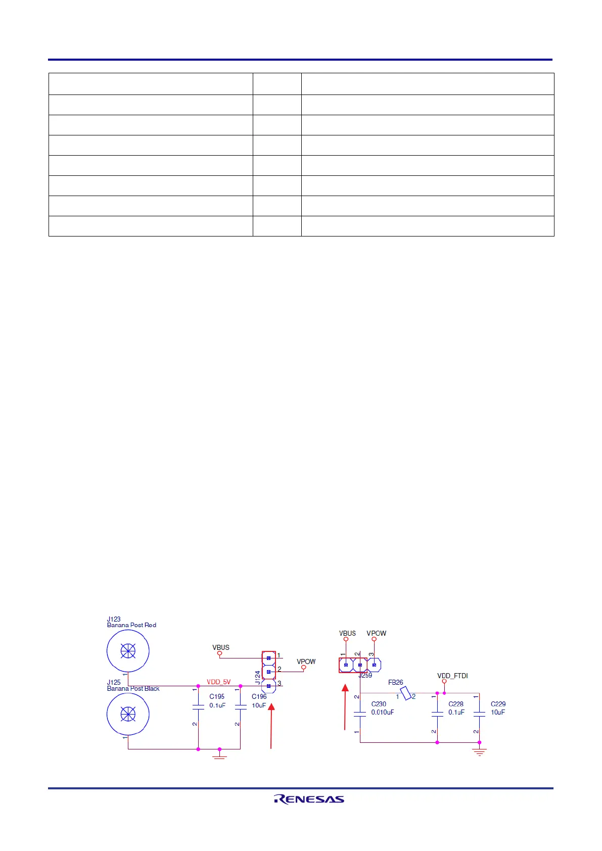
1.2.1.1. Power the Device with USB Connection
■
Set jumper on J124 between pins 1 and 2
■
Set jumper on J259 between pins 1 and 2
■
Ensure that the EVB connects to a USB 3.0 port or newer
Figure 3. USB Power Jumpers
 Loading...


