RC22312A/RC32312A Evaluation Board Manual
R31UH0022EU0100 Rev.1.00
Mar 28, 2023
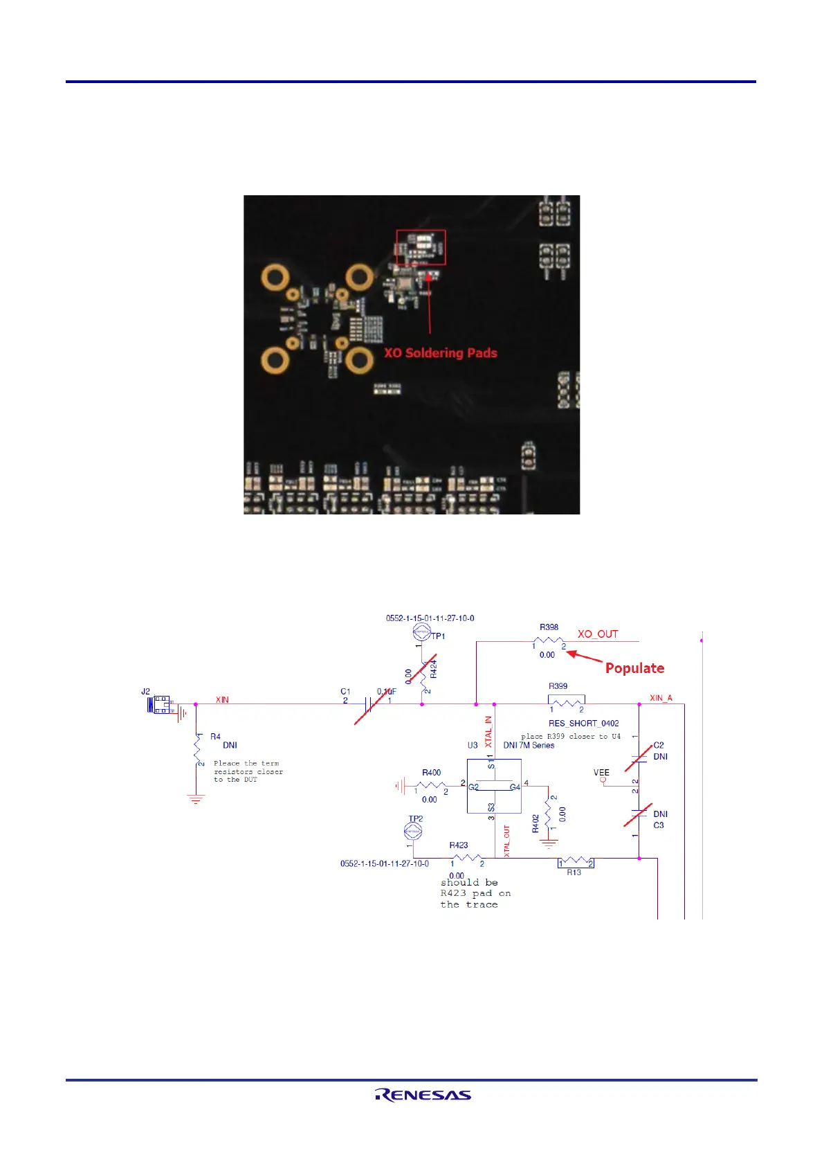
1.2.4. On-board XO Mount
There are two options on the evaluation board to allow for an XO to be mounted. Positions U27 and U29 are
connected in parallel and should only be used one at a time. For an XO to work properly at U27 and U29, the
following must be setup (see Figure 10, Figure 11, Figure 12 and Figure 13):
Figure 10. EVB XO Pads
1. Populate R398 with 0 Ohms.
2. Depopulate C1, U3, R423, R424, C1, and C2.
Figure 11. XO Path Connection Schematic
3. Populate R428 if pin 5 of the XO is being used as output.
4. Ensure that the XO output is below ~1.3V amplitude signal in order to support proper XIN pin characteristics.
a. R416 can be populated with a low value resistor (33Ω) to reduce the XO output amplitude. Otherwise,
R416 can be populated with 0 Ohms.
 Loading...


