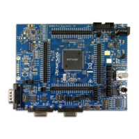
RH850/F1x StarterKit V3 User Manual
R01UH0724ED0120 Page 26
January 2018
J6 CAN0 and CAN1 transceiver NSIL to
MCU connector
1 – 2
CANNSIL0 ↔ P1_1
3 – 4
CANNSIL0 ↔ P2_6
Table 27. CAN Transceiver NSIL Jumper Configuration
The on-board CAN bus and the terminal resistors of each CAN channel can be activated by DIP
switch S4.
Enable termination resistor
Enable termination resistor
All All
Connect to on-board CAN bus
Connect to on-board CAN bus
Table 28. DIP Switch S4 - CAN Interfaces Signals
4.2.8.3 FlexRay Interface (RH850/F1H, F1KM-S4 and F1KH/D8 version only)
FLEXRAY transceiver (IC7) is supplied to provide a FLEXRAY bus interface. The transceiver can
be connected to the microcontroller’s FLEXRAY interface (FLXA). The FR bus interface is
connected to the DB9 connector CN5. The FR transceiver is enabled by default. DIP switch S7
provides additional FR bus interface configuration options including the ability to selectively
interconnect FR bus interfaces on-board.
Please close the following jumpers to connect the FLEXRAY transceiver (IC7) to the
microcontroller:
J8 FLEXRAY transceiver TX/RX to
MCU connector
1-2
FR_RXD ↔ P10_14
3-4
FR_TXEZ ↔ P10_11
5-6
FR_TXD ↔ P11_1
Table 29. FR Transceiver Jumper Configuration
The on-board FLEXRAY bus and the terminal resistors of each FLEXRAY channel can be
activated by DIP switch S7.
Transceiver Switch Note
IC7
Enable termination resistor
Enable termination resistor
Table 30. Dip Switch S7 - FR Interfaces Signals

 Loading...