E1/E20/E2/E2 Lite Additional Document 1. Overview
R20UT1994EJ0910 Rev.9.10 Page 12 of 59
Oct.06.23
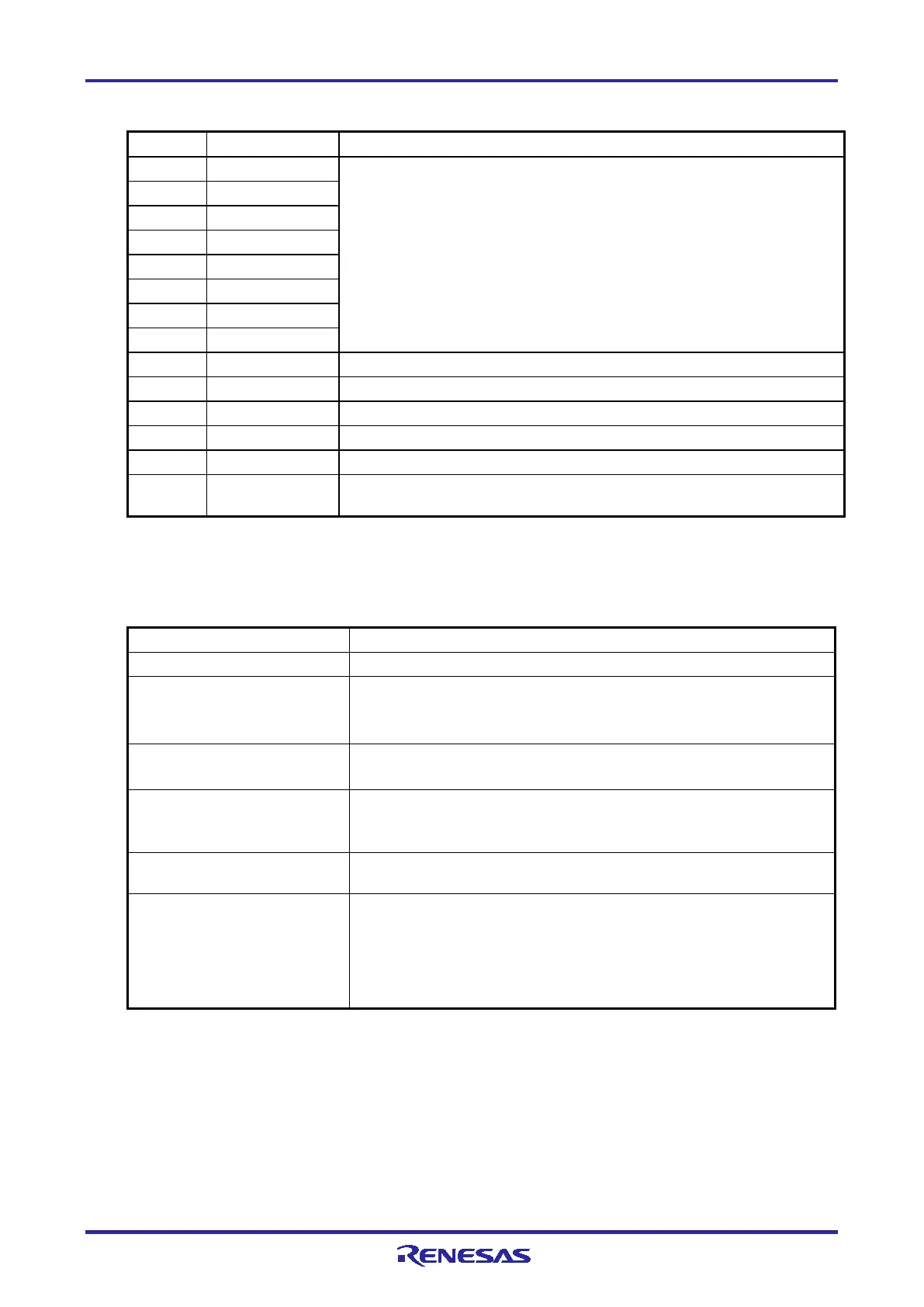
Table 1-3 Assignments of the External Trigger Input and Output Pins for the E2 Expansion Interface
Pin Nos. 1 to 8 are not used.
These pins must be left open-circuit.
3
4
7
8
External trigger output (ch. 0)
External trigger output (ch. 1)
11 Input External trigger input (ch. 0)
12 Input External trigger input (ch. 1)
A pin for output of the power-supply voltage for the E2 expansion interface
(1.8 V to 5.0 V)
1.5.2 Specifications of the External Trigger Inputs and Outputs
Table 1-4 Specifications of the External Trigger Inputs and Outputs
E2 expansion interface: 2 (ch. 0: pin 11, ch. 1: pin 12)
Output signal channels E2 expansion interface: 2 (ch. 0: pin 9, ch. 1: pin 10)
Voltage of the E2 expansion
interface
• When the power is supplied from the emulator: voltage to be supplied
(any voltage from 1.8 V to 5.0 V, as specified in the debugger)
• When the power is not supplied from the emulator: VDD voltage
Conditions for detecting an
external trigger input
Detecting edges (rising, falling, or both)
Detecting a level (low or high)
Operation during the input of an
external trigger
Recording the data from measuring the current consumption while the low
or high level is being input
Condition for detecting an
external trigger output
Detecting a break or a trigger condition for measuring the current
consumption
Operation during the output of
an external trigger
When a break is detected, a low- or high-level pulse is output (the pulse
width can be set to times in the range from 1 µs to 65535 µs).
When a trigger condition for measuring the current consumption is
detected, a high-level pulse is output (the pulse width can be set to times
in the range from 1 µs to 65535 µs). Otherwise, a high level is output while
a condition is being satisfied.
Note: About 12 µs will be required from the detection of a condition for an external trigger input being satisfied until the
user program is stopped.

 Loading...


