E1/E20/E2/E2 Lite Additional Document 2. Designing the User System
R20UT1994EJ0910 Rev.9.10 Page 19 of 59
Oct.06.23
2.4 Recommended Circuits between the Connector and the MCU
This section shows recommended circuits for connection between the connector and the MCU when the
E1/E20/E2/E2 Lite is in use. For processing of signals, refer to section 2.5, Notes on Connection.
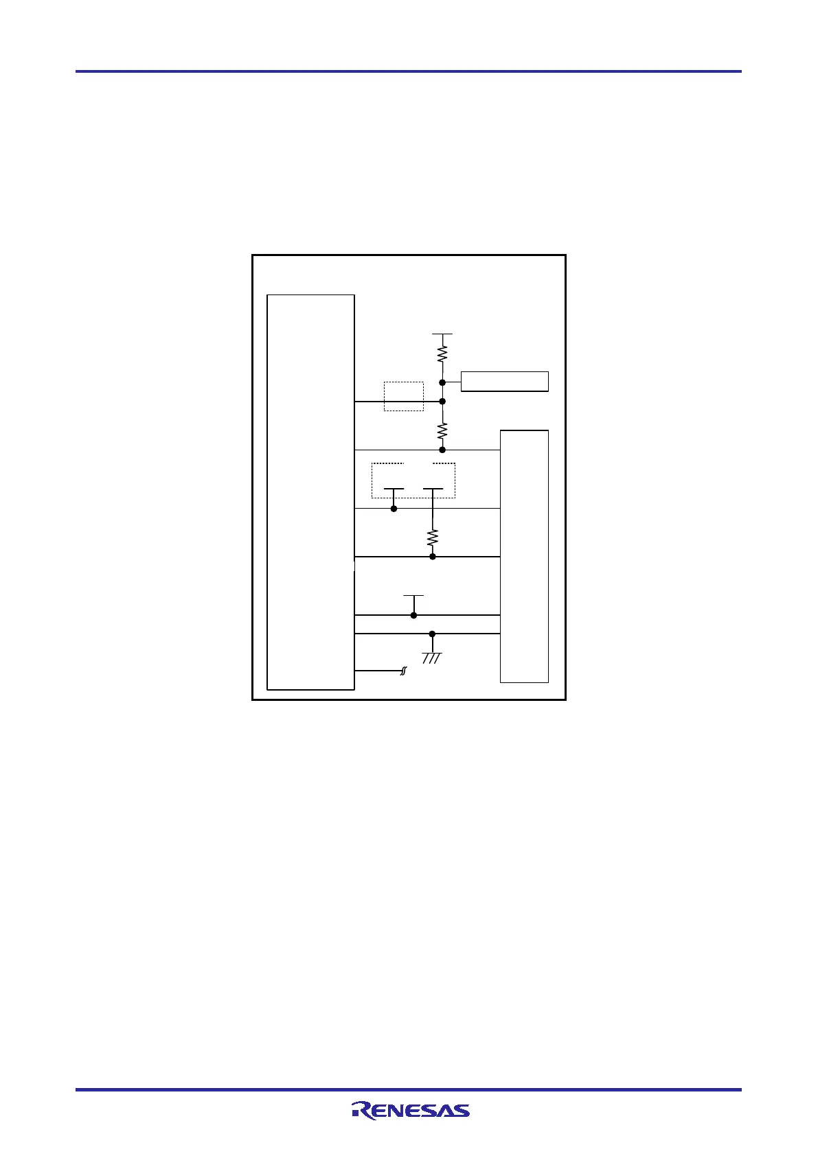
2.4.1 Connection between the 14-Pin Connector and the RL78 Family MCUs in General
Figure 2-5 shows a recommended circuit for connection between the 14-pin connector and the RL78 family
MCUs in general.
MCU
8
VSS
14-pin 2.54-mm pitch
connector
VDD
9 EVDD
2,12,14
5
TOOL0
TOOL0
EMVDD
VDD
VSS
10 kΩ
1 kΩ
Reset circuit
6
10,13
VDD
RESET_IN
RESET_OUT
RESET#
1 kΩ
1,3,4,7,11
R.F.U
Note 1
Note 3
Note 3
Driving power supply
for TOOL0
VDD
Note 4
Note 5
Note
6
Note 3, Note 7, Note 8
Note 5
Note 2
Figure 2-5 Example of Connection between the 14-Pin Connector and the RL78 Family MCUs in
General

 Loading...


