E1/E20/E2/E2 Lite Additional Document 2. Designing the User System
R20UT1994EJ0910 Rev.9.10 Page 35 of 59
Oct.06.23
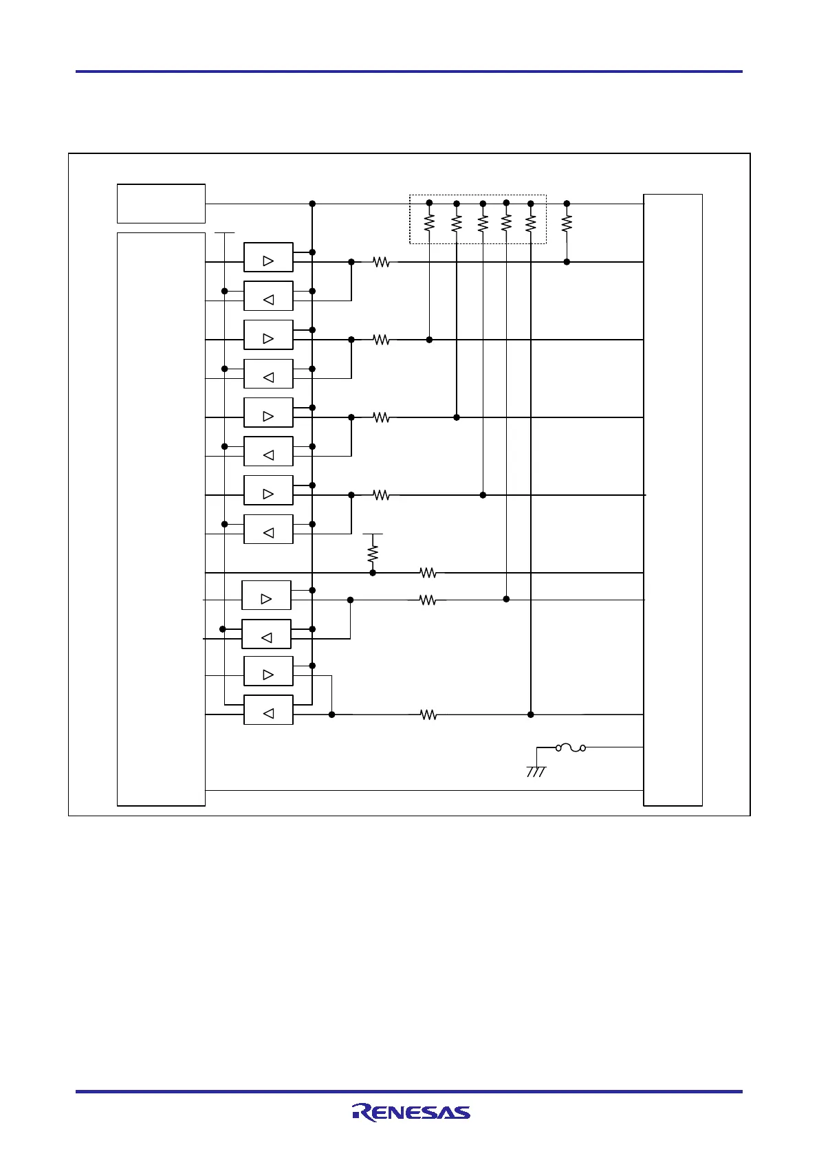
2.6.4 Internal Circuits of the E2 Lite (when the RL78 Family is Connected)
Figure 2-20 shows the internal circuits of the E2 Lite with the RL78 family connected.
Emulator
cont rol
circuit
RSTPU
VDD
4
8
47 Ω
74 LV C125
74 LV C8T24 5
3.3 V
TOOL0
5
74 LV C125
74 LV C125
74 LV C8T24 5
6
RESET_IN
74 LV C125
74 LV C8T24 5
47 Ω
10
RESET_OUT
3.3 V
47 Ω
100 kΩ
GND
14
74 LV C8T24 5
13
RESET_OUT
47 Ω
2,12
GND
Po w er-supply circuit
(only for use in the mode to
supply power to the user
sy ste m)
EMVDD
9
47 Ω
47 Ω
74 LV C8T24 5
74 LV C125
100 kΩ × 5
1 MΩ
1,3,7,11
74 LV C125
74 LV C8T24 5
47 Ω
User-side
connector
Sel f-recovering
fuse
Figure 2-20 Internal Circuits of the E2 Lite (when the RL78 Family is Connected)

 Loading...


